How to Use BD677 NPN Darlington Transistor: Examples, Pinouts, and Specs
Introduction
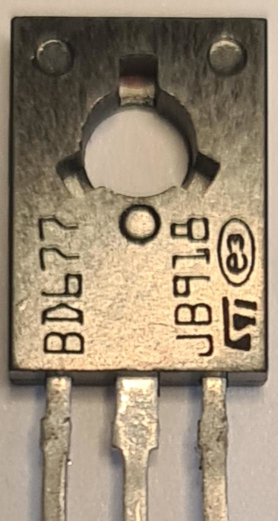
The BD677 is a monolithic NPN Darlington transistor manufactured by STMicroelectronics. It is designed for general-purpose amplifier and low-speed switching applications. The high current gain and collector current rating make it suitable for interfacing with high-power loads in various electronic circuits.
Explore Projects Built with BD677 NPN Darlington Transistor
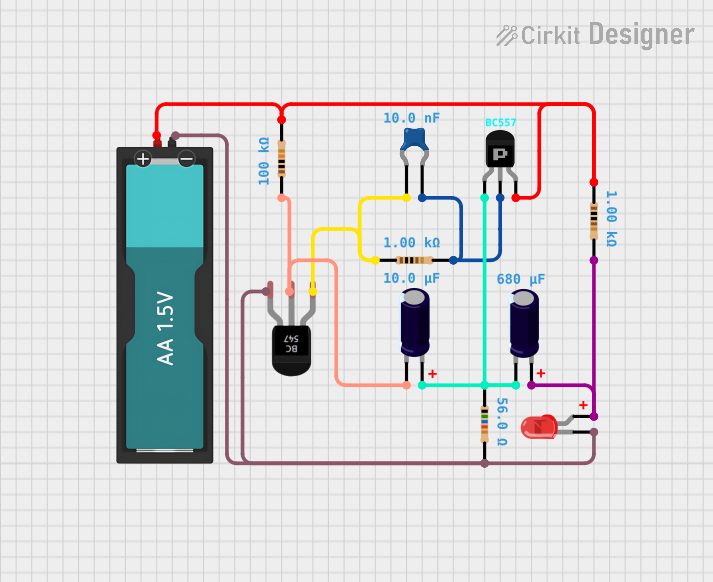

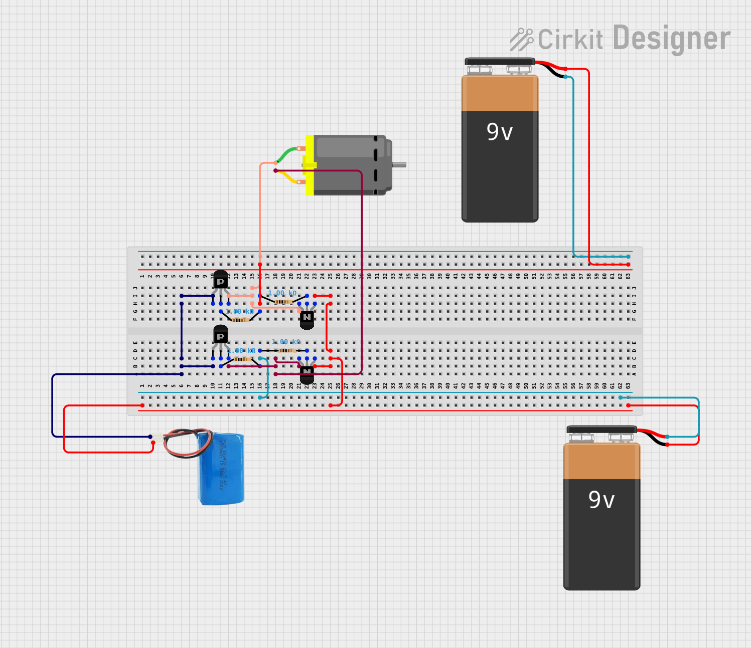

Explore Projects Built with BD677 NPN Darlington Transistor
Common Applications and Use Cases
- Motor drivers
- Relay drivers
- Audio amplifiers
- Power regulators
- Solenoid/actuator drivers
Technical Specifications
Key Technical Details
- Transistor Type: NPN Darlington
- Collector-Emitter Voltage (Vceo): 60V
- Collector-Base Voltage (Vcbo): 60V
- Emitter-Base Voltage (Vebo): 5V
- Collector Current (Ic): 4A
- DC Current Gain (hFE): 750 (minimum) at Ic = 2A
- Power Dissipation (Pd): 40W
- Operating Junction Temperature (Tj): -65°C to 150°C
Pin Configuration and Descriptions
| Pin Number | Name | Description |
|---|---|---|
| 1 | Base | Control input that activates the transistor |
| 2 | Collector | Connected to the load; carries the switched current |
| 3 | Emitter | Common reference for the collector and base; usually connected to ground |
Usage Instructions
How to Use the BD677 in a Circuit
- Biasing the Transistor: Apply a small current to the base pin to switch the larger current between the collector and emitter.
- Load Connection: Connect the load that needs to be switched to the collector pin.
- Emitter: Connect the emitter pin to the ground of the circuit.
- Base Resistor: Use a suitable base resistor to limit the current into the base and protect the transistor.
Important Considerations and Best Practices
- Ensure the base current is sufficient to fully saturate the transistor for full-on applications.
- Use a flyback diode when switching inductive loads to protect the transistor from voltage spikes.
- Consider heat sinking if operating near the maximum power dissipation limit.
- Avoid exceeding the maximum ratings for voltage, current, and temperature.
Troubleshooting and FAQs
Common Issues Users Might Face
- Transistor Not Switching: This could be due to insufficient base current or a faulty transistor.
- Overheating: Caused by excessive power dissipation or overcurrent.
- Unexpected Voltage Drops: Check for proper saturation and that the load does not exceed the transistor's current rating.
Solutions and Tips for Troubleshooting
- Verify the base current is adequate for the desired collector current.
- Check for proper heat sinking and airflow around the transistor.
- Ensure the power supply and load are within the transistor's specifications.
FAQs
Q: Can the BD677 be driven directly from a microcontroller?
- A: Yes, but ensure that the base current is limited with a resistor and does not exceed the microcontroller's maximum current rating.
Q: What is the function of the Darlington pair in this transistor?
- A: The Darlington pair configuration provides a high current gain, allowing the transistor to be controlled with a very small base current.
Q: Is the BD677 suitable for AC loads?
- A: No, it is designed for DC applications.
Example Arduino UNO Code
The following example demonstrates how to use the BD677 to switch a DC motor on and off with an Arduino UNO.
// Define the pin connected to the base of the BD677
const int transistorPin = 9;

void setup() {
  // Set the transistor pin as an output
  pinMode(transistorPin, OUTPUT);
}

void loop() {
  // Turn on the motor by applying a HIGH signal to the base of the BD677
  digitalWrite(transistorPin, HIGH);
  delay(1000); // Motor runs for 1 second

  // Turn off the motor by applying a LOW signal to the base
  digitalWrite(transistorPin, LOW);
  delay(1000); // Motor is off for 1 second
}
Note: Remember to include a suitable base resistor between the Arduino pin and the base of the BD677 to limit the base current. The value of the resistor can be calculated based on the desired base current and the voltage level from the Arduino pin.