How to Use IR: Examples, Pinouts, and Specs
Introduction
Infrared (IR) components are electronic devices designed to transmit and receive infrared light, which is electromagnetic radiation with wavelengths longer than visible light but shorter than microwaves. These components are widely used in applications such as remote controls, proximity sensors, object detection, and wireless communication systems. IR components are essential in enabling non-contact communication and sensing in a variety of consumer electronics, industrial systems, and IoT devices.
Common applications include:
- Remote controls for TVs, air conditioners, and other appliances
- Proximity and obstacle detection in robotics
- Data transmission in wireless communication systems
- Motion detection in security systems
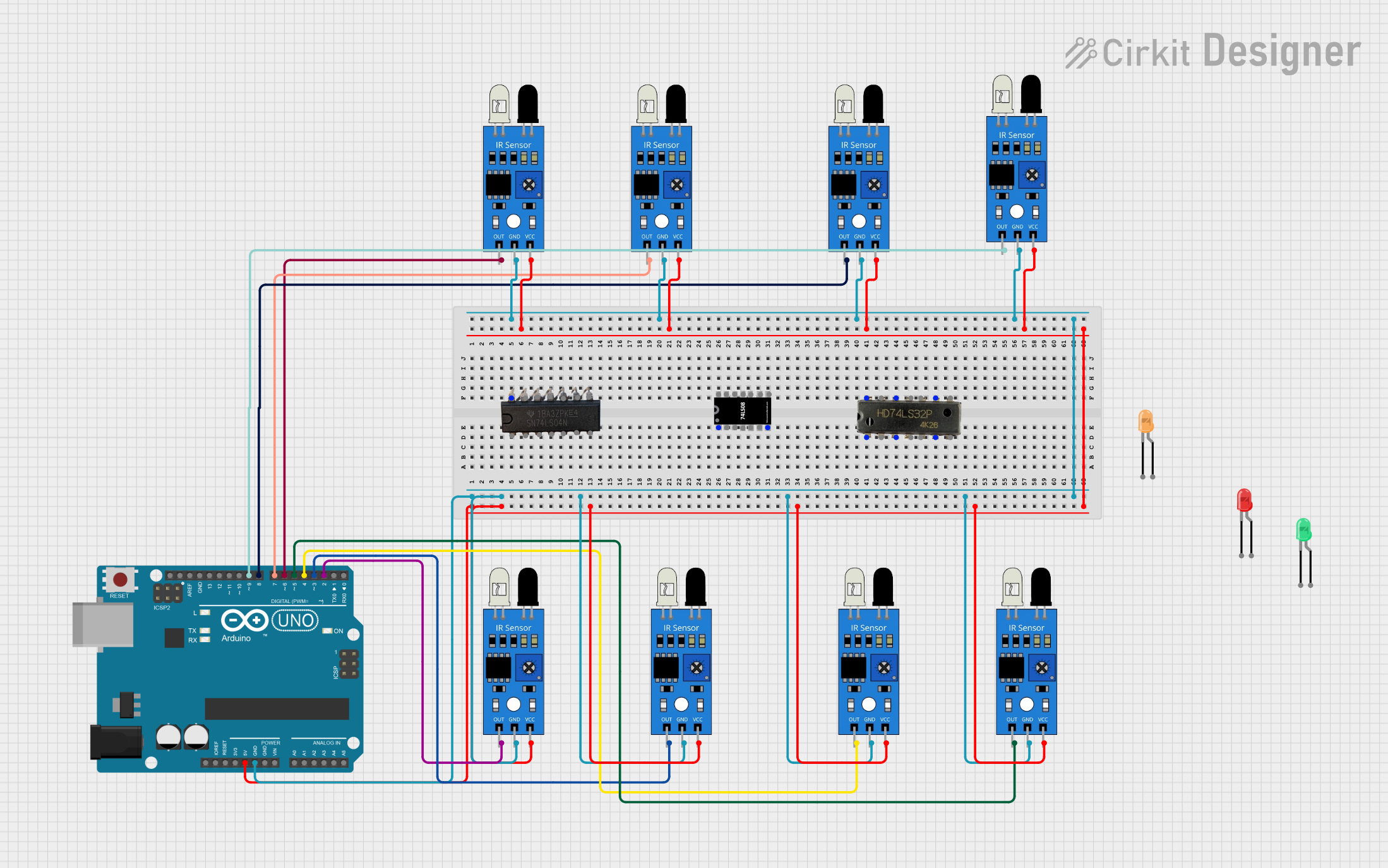
- Line-following robots and automation systems
Explore Projects Built with IR
Explore Projects Built with IR
Technical Specifications
General Specifications
| Parameter | Value |
|---|---|
| Wavelength Range | 700 nm to 1 mm (Infrared spectrum) |
| Operating Voltage | 2.7V to 5.5V (varies by component) |
| Current Consumption | Typically 10-50 mA |
| Communication Protocols | Modulated IR signals (e.g., 38 kHz) |
| Transmission Range | Up to 10 meters (depending on power) |
Pin Configuration and Descriptions
IR Transmitter (LED)
| Pin Number | Name | Description |
|---|---|---|
| 1 | Anode (+) | Connect to the positive terminal of the power supply. |
| 2 | Cathode (-) | Connect to ground. |
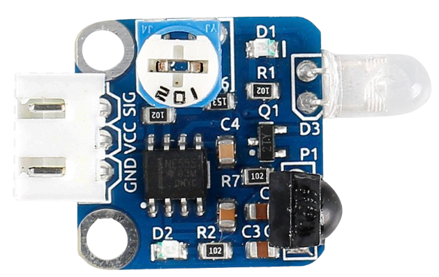
IR Receiver (Photodiode or Phototransistor)
| Pin Number | Name | Description |
|---|---|---|
| 1 | VCC | Connect to the positive terminal of the power supply. |
| 2 | GND | Connect to ground. |
| 3 | OUT | Outputs the detected signal (digital or analog). |
Usage Instructions
How to Use the Component in a Circuit
- IR Transmitter: Connect the anode of the IR LED to a current-limiting resistor (typically 220Ω to 1kΩ) and then to the power supply. The cathode should be connected to ground. The IR LED emits infrared light when powered.
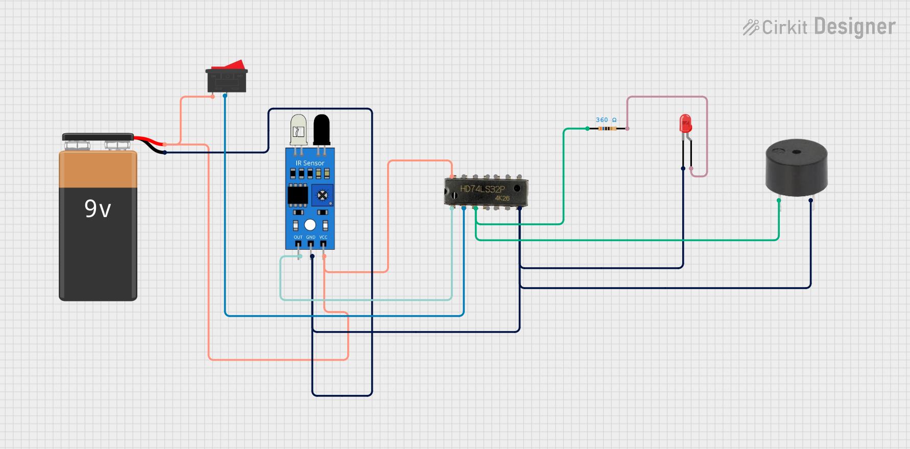
- IR Receiver: Connect the VCC pin to the power supply and the GND pin to ground. The OUT pin will output a signal based on the received infrared light. For digital receivers, the output is typically HIGH or LOW, while analog receivers provide a variable voltage.
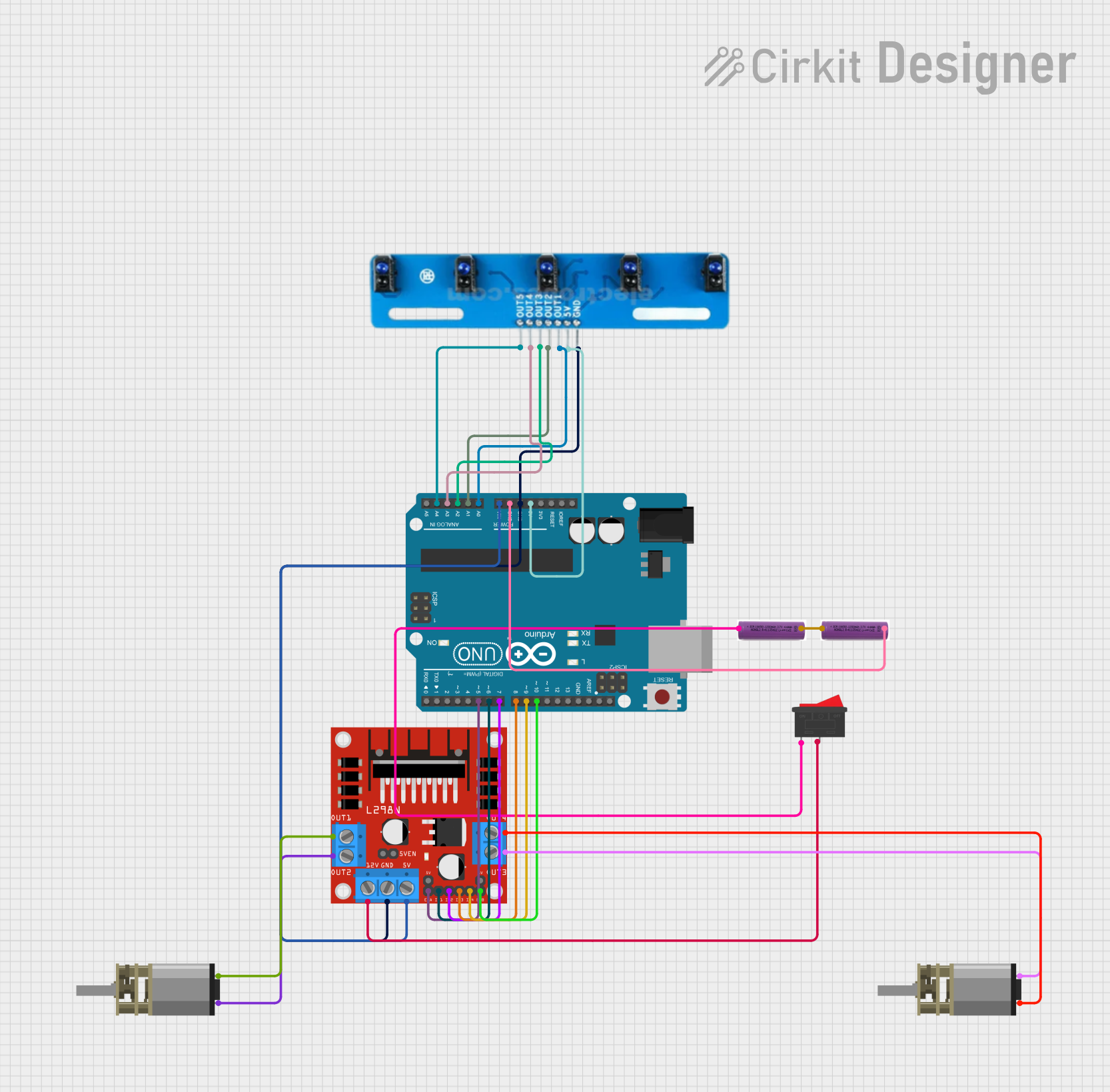
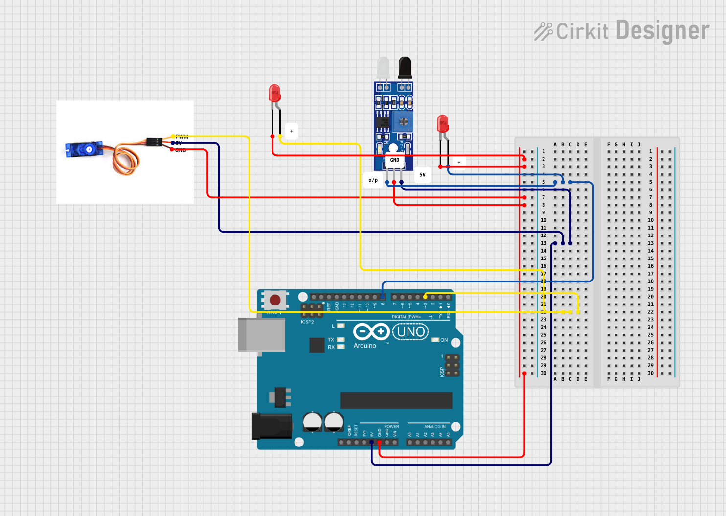
Example Circuit with Arduino UNO
Below is an example of using an IR transmitter and receiver with an Arduino UNO to detect obstacles:
Circuit Connections
- Connect the IR LED anode to Arduino pin 3 (via a 220Ω resistor) and the cathode to GND.
- Connect the IR receiver's VCC to 5V, GND to GND, and OUT to Arduino pin 2.
Arduino Code
// IR Obstacle Detection Example
// Connect IR LED to pin 3 and IR receiver OUT to pin 2

const int irLedPin = 3;  // Pin connected to IR LED
const int irReceiverPin = 2;  // Pin connected to IR receiver OUT

void setup() {
  pinMode(irLedPin, OUTPUT);  // Set IR LED pin as output
  pinMode(irReceiverPin, INPUT);  // Set IR receiver pin as input
  Serial.begin(9600);  // Initialize serial communication
}

void loop() {
  digitalWrite(irLedPin, HIGH);  // Turn on IR LED
  delay(10);  // Short delay to stabilize the signal

  int irSignal = digitalRead(irReceiverPin);  // Read IR receiver output

  if (irSignal == LOW) {
    // LOW indicates an obstacle is detected
    Serial.println("Obstacle detected!");
  } else {
    // HIGH indicates no obstacle
    Serial.println("No obstacle.");
  }

  delay(500);  // Wait before the next reading
}
Important Considerations and Best Practices
- Use a current-limiting resistor with the IR LED to prevent damage.
- Ensure proper alignment between the IR transmitter and receiver for optimal performance.
- Avoid interference from ambient light by using modulated IR signals (e.g., 38 kHz) and a corresponding receiver.
- For longer transmission distances, use a higher-power IR LED and a lens to focus the beam.
Troubleshooting and FAQs
Common Issues and Solutions
IR Receiver Not Detecting Signals
- Ensure the IR LED is functioning and properly aligned with the receiver.
- Check the connections and verify the power supply voltage.
- Use a modulated IR signal if ambient light interference is an issue.
Short Transmission Range
- Verify the current-limiting resistor value for the IR LED. A lower resistance increases brightness but ensure it does not exceed the LED's current rating.
- Use a higher-power IR LED or a lens to focus the beam.
False Detections
- Shield the IR receiver from ambient light sources.
- Use a modulated IR signal to reduce interference.
FAQs
Q: Can I use an IR component outdoors?
A: Yes, but ambient sunlight can interfere with the IR signal. Use modulated signals and shield the receiver for better performance.
Q: What is the typical range of an IR transmitter and receiver?
A: The range depends on the power of the IR LED and the sensitivity of the receiver. Typical ranges are 5-10 meters indoors.
Q: Can I use an IR receiver with a TV remote?
A: Yes, most TV remotes use modulated IR signals (e.g., 38 kHz), which are compatible with standard IR receivers.
By following this documentation, you can effectively integrate IR components into your projects for reliable infrared communication and sensing.