How to Use LASER TREE: Examples, Pinouts, and Specs
Introduction
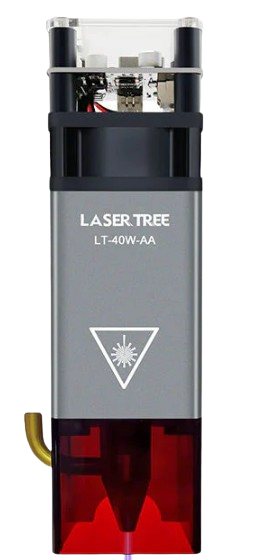
A Laser Tree is a specialized optical device that utilizes multiple laser beams arranged in a tree-like structure. This configuration allows for precise control and distribution of laser light, making it an essential component in advanced optical systems. Laser Trees are commonly used in applications such as telecommunications, optical sensing, imaging systems, and scientific research. Their ability to split and direct laser beams with high accuracy makes them invaluable in scenarios requiring complex optical routing.
Explore Projects Built with LASER TREE
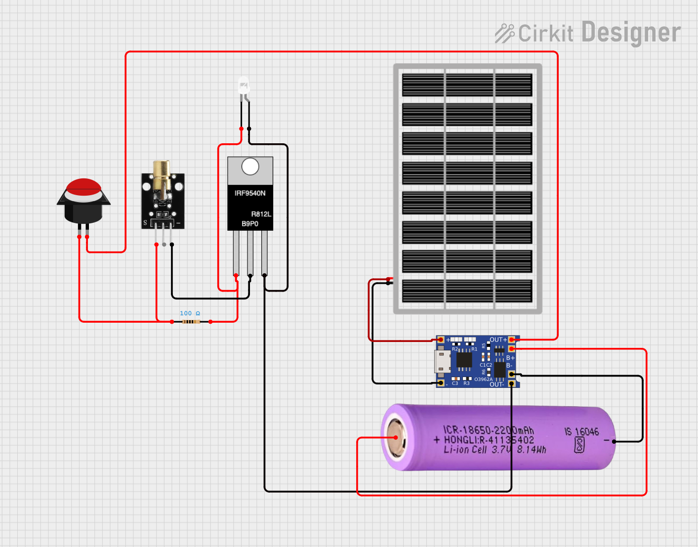
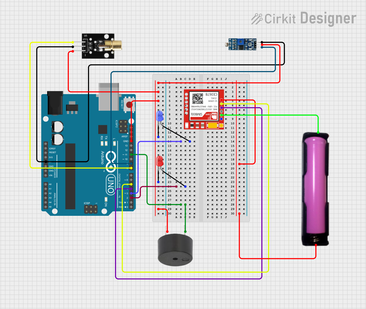
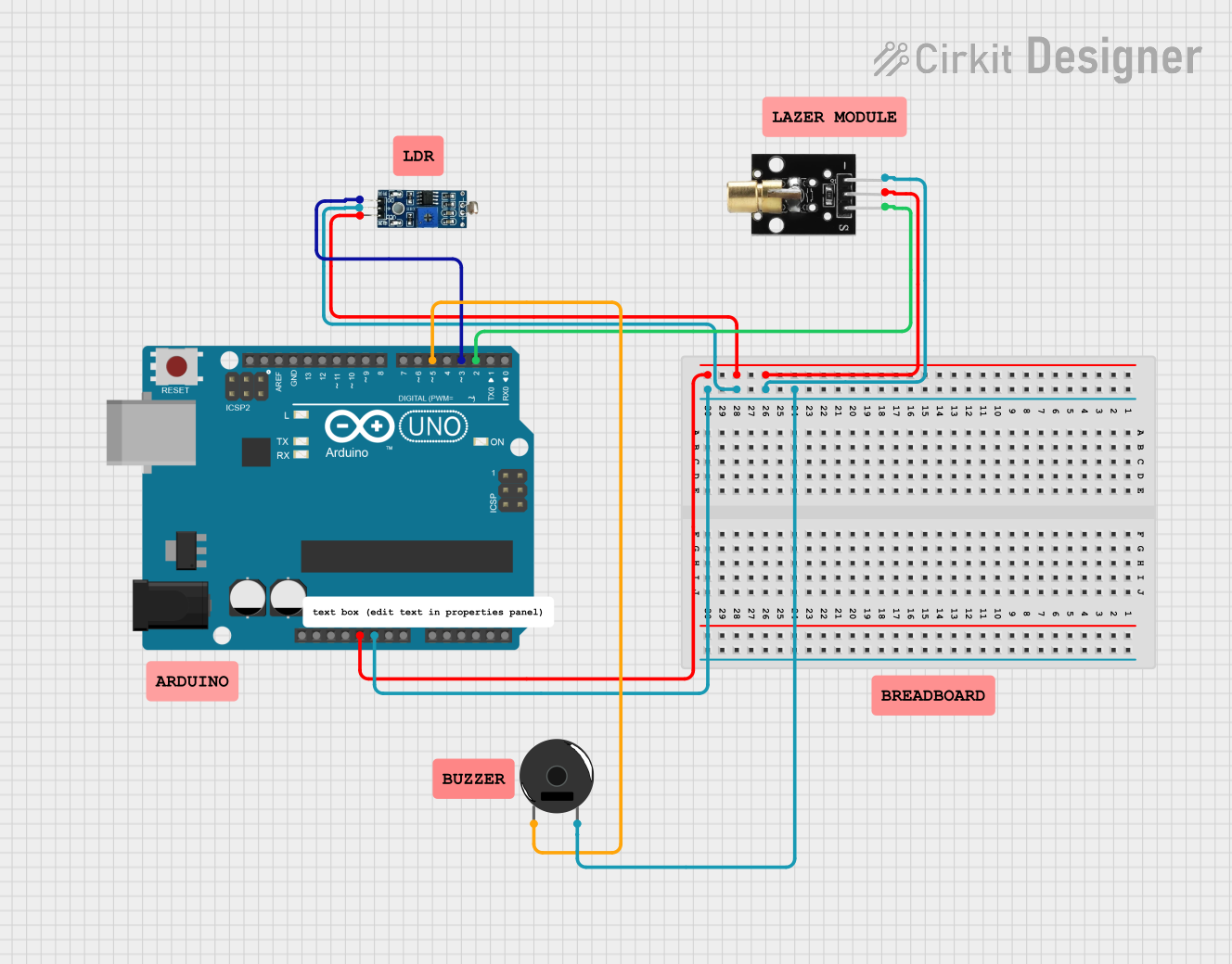
Explore Projects Built with LASER TREE
Technical Specifications
Below are the key technical details and pin configuration for a typical Laser Tree device:
Key Technical Details
| Parameter | Value/Range |
|---|---|
| Wavelength Range | 400 nm to 1550 nm |
| Input Power | 1 mW to 10 W (depending on model) |
| Beam Divergence | < 1 mrad |
| Operating Temperature | -20°C to 70°C |
| Storage Temperature | -40°C to 85°C |
| Optical Efficiency | > 90% |
| Material | High-grade optical glass or quartz |
| Control Interface | Analog or Digital (depending on model) |
Pin Configuration and Descriptions
| Pin Number | Pin Name | Description |
|---|---|---|
| 1 | Input Laser | Connects to the input laser source |
| 2 | Output Beam 1 | First output beam from the tree structure |
| 3 | Output Beam 2 | Second output beam from the tree structure |
| 4 | Output Beam 3 | Third output beam from the tree structure |
| 5 | Ground (GND) | Ground connection for the device |
| 6 | Control Signal | Input for controlling beam splitting or routing |
Usage Instructions
How to Use the Laser Tree in a Circuit
- Power Supply: Ensure the Laser Tree is connected to a stable power source within its specified input power range.
- Input Laser Connection: Connect the input laser source to the
Input Laserpin. Ensure the wavelength and power of the laser source are compatible with the Laser Tree's specifications. - Output Beam Connections: Connect the desired optical components (e.g., sensors, detectors, or mirrors) to the output beam pins (
Output Beam 1,Output Beam 2, etc.). - Control Signal: If the Laser Tree supports beam routing or splitting control, connect the control signal to the
Control Signalpin. Use an appropriate analog or digital signal as specified in the datasheet. - Grounding: Connect the
Ground (GND)pin to the circuit's ground to ensure proper operation.
Important Considerations and Best Practices
- Laser Safety: Always use appropriate laser safety goggles and follow safety guidelines when working with laser devices.
- Alignment: Ensure precise alignment of the input laser source to maximize optical efficiency.
- Thermal Management: If operating at high power levels, consider using a heat sink or active cooling to prevent overheating.
- Signal Integrity: Use shielded cables for the control signal to minimize noise and interference.
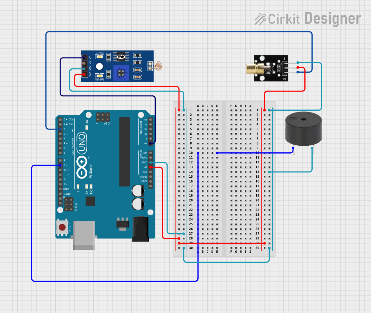
Example: Connecting a Laser Tree to an Arduino UNO
If the Laser Tree supports digital control, you can use an Arduino UNO to manage the beam routing. Below is an example code snippet:
// Example code to control a Laser Tree using Arduino UNO
// This code assumes the Laser Tree's control signal is connected to pin 9

const int controlPin = 9; // Pin connected to the Laser Tree's control signal

void setup() {
  pinMode(controlPin, OUTPUT); // Set the control pin as an output
}

void loop() {
  digitalWrite(controlPin, HIGH); // Activate beam routing
  delay(1000); // Keep the beam active for 1 second

  digitalWrite(controlPin, LOW); // Deactivate beam routing
  delay(1000); // Wait for 1 second before reactivating
}
Troubleshooting and FAQs
Common Issues and Solutions
| Issue | Possible Cause | Solution |
|---|---|---|
| No output from the Laser Tree | Incorrect input laser connection | Verify the input laser source and alignment. |
| Weak or distorted output beams | Misalignment of optical components | Realign the input laser and output optics. |
| Overheating | Excessive input power or poor ventilation | Reduce input power or improve cooling. |
| Control signal not working | Incorrect signal type or wiring issue | Check the control signal type and connections. |
FAQs
Can I use any laser source with the Laser Tree?
No, ensure the laser source's wavelength and power are within the Laser Tree's specifications.What happens if the input power exceeds the specified range?
Exceeding the input power range can damage the Laser Tree or reduce its lifespan. Always operate within the recommended range.Can the Laser Tree operate in outdoor environments?
Some models are designed for outdoor use, but ensure the device is rated for the environmental conditions (e.g., temperature, humidity).How do I clean the optical surfaces?
Use a lint-free cloth and an appropriate optical cleaning solution. Avoid touching the surfaces with bare hands.
By following this documentation, you can effectively integrate and operate a Laser Tree in your optical systems.