
How to Use 24co2: Examples, Pinouts, and Specs
 Design with 24co2 in Cirkit Designer
Introduction
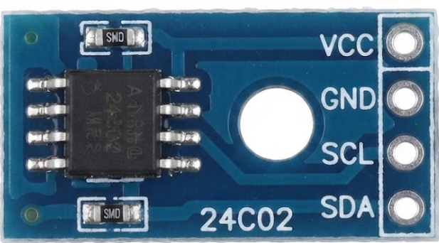
The 24CO2 is a carbon dioxide (CO2) sensor designed to measure the concentration of CO2 in the air. It is widely used in applications such as HVAC (Heating, Ventilation, and Air Conditioning) systems, indoor air quality monitoring, and environmental data collection. This sensor provides accurate and reliable measurements, making it an essential component for systems that require real-time CO2 monitoring.
Explore Projects Built with 24co2
 Open Project in Cirkit Designer
 Open Project in Cirkit Designer
 Open Project in Cirkit Designer
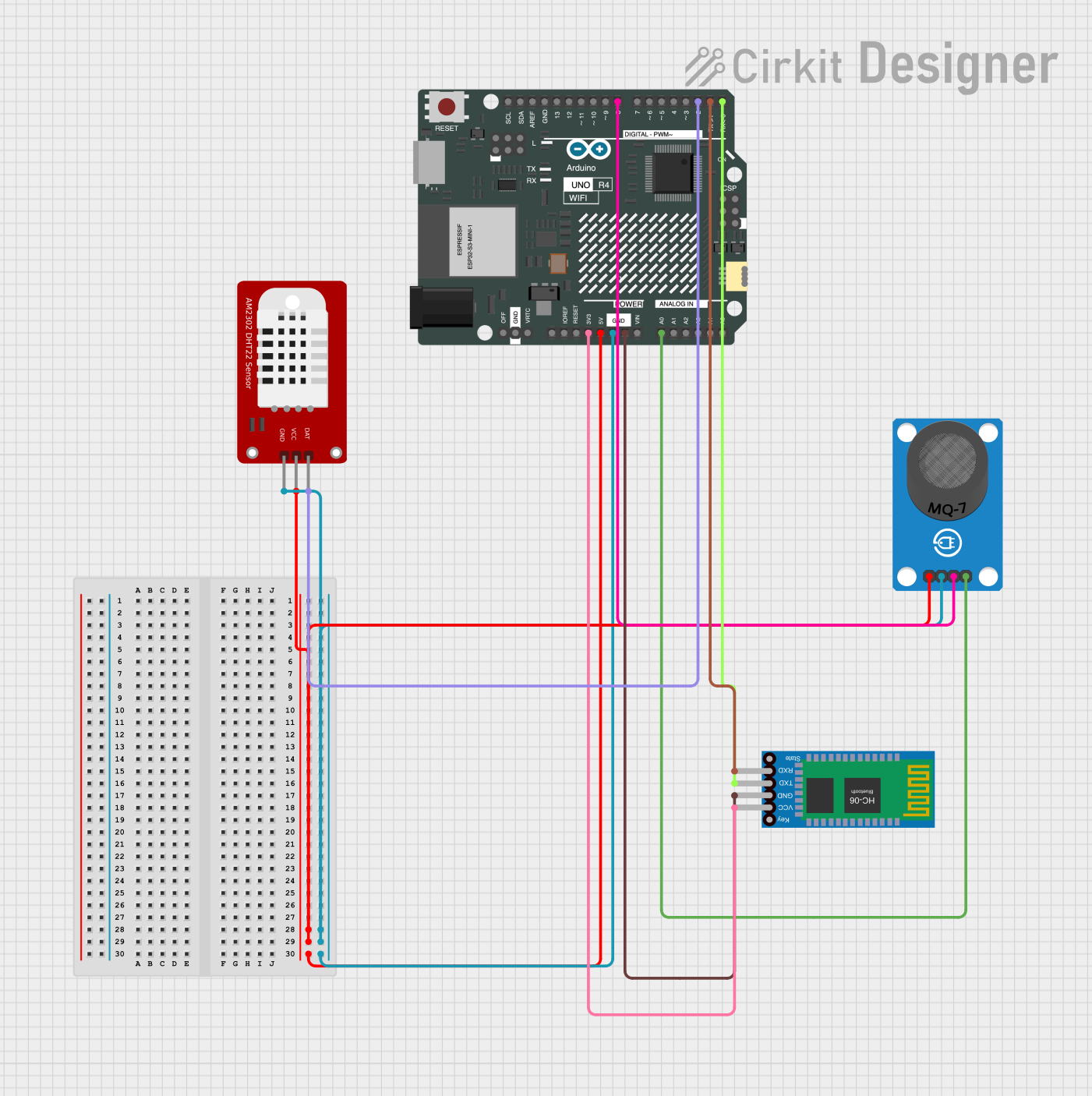 Open Project in Cirkit Designer
Explore Projects Built with 24co2
Open Project in Cirkit DesignerOpen Project in Cirkit DesignerOpen Project in Cirkit DesignerOpen Project in Cirkit DesignerCommon Applications and Use Cases
- HVAC systems for maintaining optimal air quality
- Indoor air quality monitoring in homes, offices, and schools
- Greenhouse CO2 level monitoring for plant growth optimization
- Industrial safety systems to detect elevated CO2 levels
- Environmental monitoring and research projects
Technical Specifications
The 24CO2 sensor is designed to operate efficiently in a variety of environments. Below are its key technical details:
| Parameter | Value |
|---|---|
| Measurement Range | 0 - 5000 ppm (parts per million) |
| Accuracy | ±50 ppm or ±3% of reading |
| Operating Voltage | 3.3V - 5V DC |
| Operating Current | < 50 mA |
| Output Signal | Analog voltage or UART (serial) |
| Warm-Up Time | < 2 minutes |
| Operating Temperature | -10°C to 50°C |
| Operating Humidity | 0% - 95% RH (non-condensing) |
| Dimensions | 35mm x 25mm x 10mm |
Pin Configuration and Descriptions
The 24CO2 sensor typically has a 4-pin interface. The pinout is as follows:
| Pin | Name | Description |
|---|---|---|
| 1 | VCC | Power supply input (3.3V - 5V DC) |
| 2 | GND | Ground connection |
| 3 | OUT | Analog output signal proportional to CO2 concentration |
| 4 | TX | UART serial data output |
Usage Instructions
How to Use the 24CO2 in a Circuit
- Power Supply: Connect the VCC pin to a 3.3V or 5V DC power source and the GND pin to the ground of your circuit.
- Signal Output:
- For analog output, connect the OUT pin to an analog input pin of your microcontroller.
- For UART communication, connect the TX pin to the RX pin of your microcontroller.
- Warm-Up Time: Allow the sensor to warm up for at least 2 minutes after powering it on to ensure accurate readings.
- Data Reading:
- If using the analog output, read the voltage from the OUT pin and convert it to CO2 concentration using the sensor's datasheet-provided formula.
- If using UART, read the serial data from the TX pin and parse the CO2 concentration value.
Important Considerations and Best Practices
- Power Stability: Ensure a stable power supply to avoid fluctuations in sensor readings.
- Ventilation: Place the sensor in a well-ventilated area to avoid CO2 buildup around the sensor.
- Calibration: Periodically calibrate the sensor as per the manufacturer's instructions to maintain accuracy.
- Avoid Condensation: Operate the sensor in non-condensing environments to prevent damage.
Example: Connecting the 24CO2 to an Arduino UNO
Below is an example of how to connect and read data from the 24CO2 sensor using an Arduino UNO:
Circuit Connections
- Connect the VCC pin of the 24CO2 to the 5V pin of the Arduino.
- Connect the GND pin of the 24CO2 to the GND pin of the Arduino.
- Connect the OUT pin of the 24CO2 to the A0 pin of the Arduino (for analog output).
- Alternatively, connect the TX pin of the 24CO2 to the RX pin of the Arduino (for UART).
Arduino Code
// 24CO2 Sensor Example Code for Arduino UNO
// This code reads the analog output from the sensor and calculates CO2 concentration.

const int sensorPin = A0; // Analog pin connected to the OUT pin of the 24CO2 sensor
float voltage;            // Variable to store the sensor output voltage
float co2Concentration;   // Variable to store the calculated CO2 concentration

void setup() {
  Serial.begin(9600); // Initialize serial communication at 9600 baud
  pinMode(sensorPin, INPUT); // Set the sensor pin as input
}

void loop() {
  // Read the analog voltage from the sensor
  int sensorValue = analogRead(sensorPin);

  // Convert the analog value to voltage (assuming 5V reference)
  voltage = sensorValue * (5.0 / 1023.0);

  // Convert the voltage to CO2 concentration (example formula, refer to datasheet)
  co2Concentration = (voltage - 0.4) * 2000.0; // Adjust based on sensor specs

  // Print the CO2 concentration to the Serial Monitor
  Serial.print("CO2 Concentration: ");
  Serial.print(co2Concentration);
  Serial.println(" ppm");

  delay(1000); // Wait for 1 second before the next reading
}
Troubleshooting and FAQs
Common Issues and Solutions
No Output Signal:
- Ensure the sensor is properly powered (check VCC and GND connections).
- Verify that the warm-up time has elapsed before taking readings.
Inaccurate Readings:
- Check for stable power supply and proper grounding.
- Ensure the sensor is not exposed to extreme temperatures or humidity.
- Perform a calibration if readings deviate significantly from expected values.
UART Communication Issues:
- Verify the baud rate matches the sensor's default setting (typically 9600 baud).
- Check the TX and RX connections between the sensor and microcontroller.
FAQs
Q: Can the 24CO2 sensor be used outdoors?
A: The sensor is designed for indoor use and should be protected from extreme weather conditions and condensation if used outdoors.
Q: How often should the sensor be calibrated?
A: Calibration frequency depends on the application, but it is generally recommended to calibrate the sensor every 6-12 months.
Q: What is the warm-up time for the sensor?
A: The sensor requires less than 2 minutes of warm-up time to provide accurate readings.
Q: Can the sensor detect gases other than CO2?
A: No, the 24CO2 sensor is specifically designed to measure CO2 concentration and is not suitable for detecting other gases.