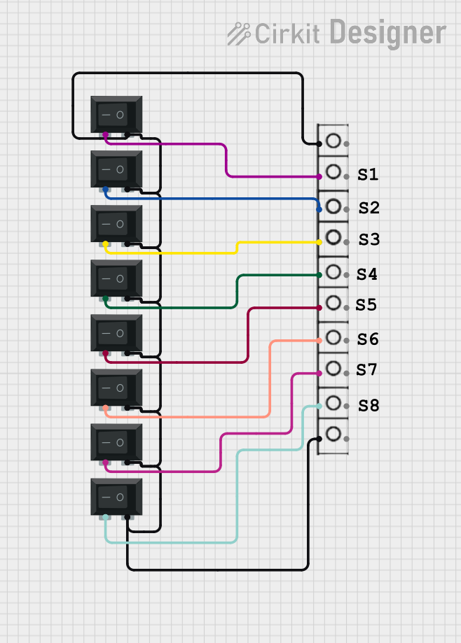
How to Use wire connector: Examples, Pinouts, and Specs

 Design with wire connector in Cirkit Designer
Introduction
A wire connector is an essential device in electrical and electronic systems, designed to securely join two or more electrical wires. These connectors ensure a reliable and safe connection, which is critical for the integrity of any electrical circuit. Wire connectors come in various forms, including screw terminals, crimped terminals, soldered joints, and twist-on connectors, each suitable for specific applications ranging from simple DIY projects to complex industrial systems.
Explore Projects Built with wire connector

 Open Project in Cirkit Designer
 Open Project in Cirkit Designer
 Open Project in Cirkit Designer
 Open Project in Cirkit Designer
Explore Projects Built with wire connector

 Open Project in Cirkit Designer
 Open Project in Cirkit Designer
 Open Project in Cirkit Designer
 Open Project in Cirkit Designer
Common Applications and Use Cases
- Home wiring for light fixtures, switches, and outlets
- Automotive wiring for connecting sensors, switches, and actuators
- Consumer electronics for internal wiring of devices
- Industrial machinery for power and signal connections
- Robotics and automation systems for connecting motors, sensors, and controllers
Technical Specifications
Key Technical Details
- Voltage Rating: The maximum voltage the connector can safely handle.
- Current Rating: The maximum current the connector can carry without overheating.
- Wire Gauge Compatibility: The range of wire sizes that the connector can accommodate.
- Material: The composition of the connector, which could be plastic, metal, or a combination, affecting its durability and conductivity.
- Insulation: Whether the connector has insulating properties to protect against short circuits and user contact.
Pin Configuration and Descriptions
| Pin Number | Description | Notes |
|---|---|---|
| N/A | Wire Entry | Where the wire is inserted |
| N/A | Connection Mechanism | The method of securing the wire |
| N/A | Insulation (if applicable) | Protective outer layer |
Note: As wire connectors do not have a standard pin configuration like integrated circuits, the table above is a generalized representation.
Usage Instructions
How to Use the Component in a Circuit
- Strip the Wire: Remove the insulation from the end of the wire to expose the bare conductor, typically 1/4 to 1/2 inch.
- Insert the Wire: Place the stripped end of the wire into the connector.
- Secure the Connection:
- For screw terminals, tighten the screw to clamp the wire.
- For crimped terminals, use a crimping tool to compress the connector around the wire.
- For twist-on connectors, twist the connector onto the wires until tight.
- Test the Connection: Gently pull on the wire to ensure it is secure and use a multimeter to check for continuity.
Important Considerations and Best Practices
- Always select a wire connector with the appropriate ratings for your application.
- Ensure the wire gauge is compatible with the connector.
- Do not overload the connector beyond its current rating.
- Use the proper tools for crimping or tightening to avoid damaging the wire or connector.
- Inspect connections regularly for signs of corrosion or wear.
Troubleshooting and FAQs
Common Issues Users Might Face
- Loose Connections: Wires may come loose if not properly secured, leading to intermittent or failed connections.
- Overheating: Exceeding the current rating can cause connectors to overheat, potentially melting the insulation or damaging the wire.
- Corrosion: Connectors exposed to moisture or certain chemicals may corrode, leading to poor conductivity.
Solutions and Tips for Troubleshooting
- Loose Connections: Re-tighten the connector's securing mechanism or re-crimp the terminal.
- Overheating: Check the current load and ensure it is within the connector's rating. Replace the connector if necessary.
- Corrosion: Clean the connector with appropriate solvents and protect it from harsh environments. Replace if corrosion is severe.
FAQs
Q: Can I reuse a wire connector? A: Some wire connectors are reusable, like screw terminals, while others, like crimped terminals, are not.
Q: How do I choose the right size connector for my wire? A: Match the wire gauge to the connector's specifications, ensuring a snug and secure fit.
Q: Is it necessary to use insulated connectors? A: Insulated connectors provide additional safety by preventing accidental contact and are recommended in most applications.
Example Code for Arduino UNO Connection
// Example code for connecting a wire to an Arduino UNO using a screw terminal connector

// No specific code is required for a wire connector as it is a passive component.
// However, ensure a secure connection between the Arduino pin and the wire.

void setup() {
  pinMode(13, OUTPUT); // Set the Arduino pin 13 as an output
}

void loop() {
  digitalWrite(13, HIGH); // Send a high signal to the wire connected to pin 13
  delay(1000);            // Wait for 1 second
  digitalWrite(13, LOW);  // Send a low signal to the wire connected to pin 13
  delay(1000);            // Wait for 1 second
}
Note: The above code is a simple blink example to illustrate the use of an Arduino pin. The wire connector would be used to connect the wire to pin 13 securely.