How to Use Step-Down Voltage Regulator: Examples, Pinouts, and Specs
Introduction
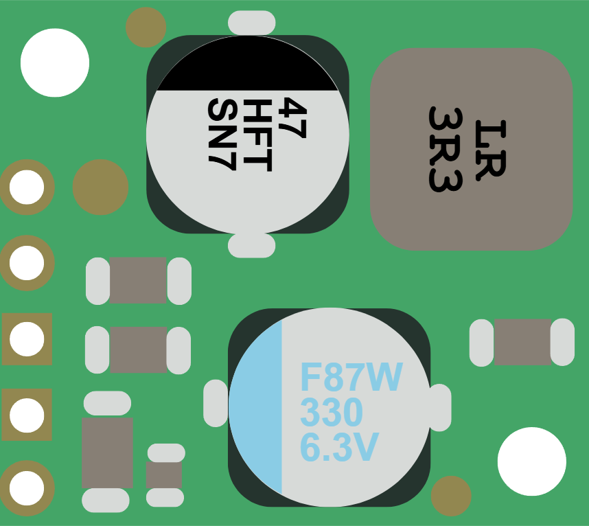
The Pololu D36V28F5 Step-Down Voltage Regulator is a high-efficiency device designed to reduce a higher input voltage to a stable 5V output. This regulator is ideal for powering low-voltage electronics from higher-voltage sources, such as batteries or power supplies. Its compact design and robust performance make it suitable for a wide range of applications, including robotics, IoT devices, and embedded systems.
Explore Projects Built with Step-Down Voltage Regulator


Explore Projects Built with Step-Down Voltage Regulator
Common Applications and Use Cases
- Powering microcontrollers, sensors, and modules from higher-voltage sources.
- Battery-powered systems requiring efficient voltage regulation.
- Robotics and automation projects.
- Portable devices and wearables.
- Replacing linear voltage regulators for improved efficiency.
Technical Specifications
Key Technical Details
- Manufacturer: Pololu
- Part ID: D36V28F5
- Input Voltage Range: 6V to 50V
- Output Voltage: 5V (fixed)
- Maximum Output Current: 2.8A
- Efficiency: Up to 90% (depending on input voltage and load)
- Quiescent Current: Approximately 1 mA
- Operating Temperature: -40°C to +85°C
- Dimensions: 0.9" × 0.6" × 0.1" (23 mm × 15 mm × 3 mm)
- Weight: 1.2 g
Pin Configuration and Descriptions
The D36V28F5 regulator has six pins, as described in the table below:
| Pin Name | Type | Description |
|---|---|---|
| VIN | Power Input | Connect to the higher input voltage (6V to 50V). |
| GND | Ground | Common ground for input and output. |
| VOUT | Power Output | Provides the regulated 5V output voltage. |
| SHDN | Shutdown Input | Active-low pin to disable the regulator. Leave unconnected or pull high to use. |
| PG | Power Good | Open-drain output that indicates if the output voltage is in regulation. |
| NC | No Connection | Not internally connected. Leave unconnected. |
Usage Instructions
How to Use the Component in a Circuit
Connect Input Voltage:
- Connect the VIN pin to your power source (6V to 50V).
- Ensure the input voltage is within the specified range to avoid damage.
Connect Ground:
- Connect the GND pin to the ground of your circuit.
Connect Output Voltage:
- Connect the VOUT pin to the load that requires a 5V supply.
- Ensure the load does not exceed the maximum output current of 2.8A.
Optional Connections:
- Use the SHDN pin to enable or disable the regulator. Pull it low to disable or leave it unconnected to enable.
- Monitor the PG pin to check if the output voltage is in regulation.
Important Considerations and Best Practices
- Input Voltage Range: Always ensure the input voltage is within the 6V to 50V range. Exceeding this range can damage the regulator.
- Heat Dissipation: At high currents, the regulator may generate heat. Ensure adequate ventilation or use a heatsink if necessary.
- Capacitors: Add input and output capacitors (e.g., 10 µF ceramic capacitors) close to the regulator to improve stability and reduce noise.
- Polarity: Double-check the polarity of your connections to avoid damaging the regulator.
Example: Using with an Arduino UNO
The D36V28F5 can be used to power an Arduino UNO from a 12V battery. Below is an example circuit and code:
Circuit Connections
- Connect the 12V battery's positive terminal to the VIN pin of the regulator.
- Connect the battery's negative terminal to the GND pin of the regulator.
- Connect the VOUT pin of the regulator to the 5V pin of the Arduino UNO.
- Connect the GND pin of the regulator to the GND pin of the Arduino UNO.
Example Code
// Example code for Arduino UNO powered by Pololu D36V28F5 regulator
// This code blinks an LED connected to pin 13

void setup() {
  pinMode(13, OUTPUT); // Set pin 13 as an output
}

void loop() {
  digitalWrite(13, HIGH); // Turn the LED on
  delay(1000);            // Wait for 1 second
  digitalWrite(13, LOW);  // Turn the LED off
  delay(1000);            // Wait for 1 second
}
Troubleshooting and FAQs
Common Issues and Solutions
| Issue | Possible Cause | Solution |
|---|---|---|
| Regulator not providing 5V output | Input voltage is out of range | Ensure the input voltage is between 6V and 50V. |
| Regulator overheating | Excessive load current or poor ventilation | Reduce the load current or improve airflow around the regulator. |
| Output voltage fluctuating | Insufficient input/output capacitors | Add 10 µF ceramic capacitors close to the VIN and VOUT pins. |
| SHDN pin disabling the regulator | SHDN pin is pulled low | Leave the SHDN pin unconnected or pull it high to enable the regulator. |
| PG pin not indicating "Power Good" | Output voltage is not in regulation | Check the input voltage and load to ensure they are within specifications. |
FAQs
Can I use this regulator to power a Raspberry Pi?
Yes, but ensure the total current draw of the Raspberry Pi and peripherals does not exceed 2.8A.What happens if I exceed the input voltage range?
Exceeding the 50V input limit can permanently damage the regulator.Is the regulator protected against reverse polarity?
No, the D36V28F5 does not have reverse polarity protection. Always double-check your connections.Can I use the regulator with a solar panel?
Yes, as long as the solar panel's output voltage is within the 6V to 50V range.
This concludes the documentation for the Pololu D36V28F5 Step-Down Voltage Regulator.