How to Use Rush Blade F7: Examples, Pinouts, and Specs
Introduction
The Rush Blade F7 by FC is a high-performance electronic component designed for rapid switching applications. It features low resistance and high current handling capabilities, making it ideal for use in power management circuits, motor controllers, and other high-speed switching environments. Its robust design ensures reliability and efficiency in demanding applications.
Explore Projects Built with Rush Blade F7


Explore Projects Built with Rush Blade F7
Common Applications
- Power management circuits
- Motor controllers
- DC-DC converters
- High-speed switching circuits
- Robotics and automation systems
Technical Specifications
The following table outlines the key technical details of the Rush Blade F7:
| Parameter | Value |
|---|---|
| Manufacturer | FC |
| Part ID | Rush Blade F7 |
| Operating Voltage Range | 3.3V to 24V |
| Maximum Current Rating | 50A |
| Switching Frequency | Up to 1 MHz |
| On-State Resistance (Rds) | 0.005 Ω |
| Operating Temperature | -40°C to +125°C |
| Package Type | QFN-32 |
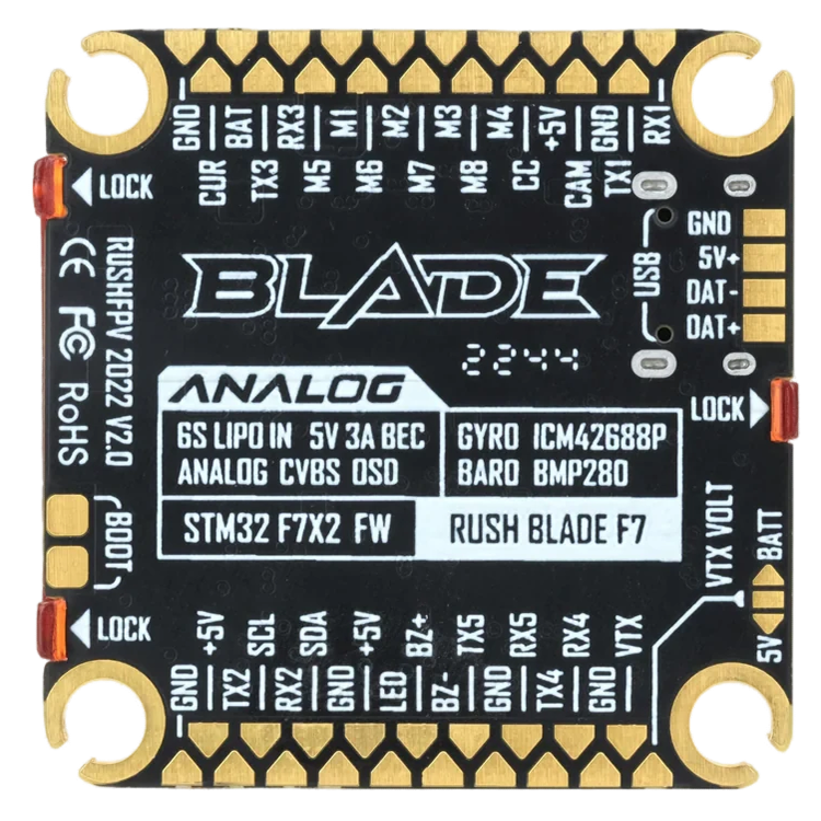
Pin Configuration and Descriptions
The Rush Blade F7 comes in a QFN-32 package with the following pin configuration:
| Pin Number | Pin Name | Description |
|---|---|---|
| 1-4 | VIN | Input voltage pins |
| 5-8 | VOUT | Output voltage pins |
| 9 | EN | Enable pin (active high) |
| 10 | GND | Ground |
| 11-14 | NC | No connection |
| 15 | PWM | PWM input for switching control |
| 16 | FB | Feedback pin for voltage regulation |
| 17-32 | Thermal Pad | Heat dissipation pad (connect to GND) |
Usage Instructions
How to Use the Rush Blade F7 in a Circuit
- Power Supply: Ensure the input voltage (VIN) is within the operating range of 3.3V to 24V.
- Enable Pin: Connect the EN pin to a logic high signal (e.g., 3.3V or 5V) to activate the component.
- PWM Control: Use the PWM pin to control the switching frequency. A typical PWM signal ranges from 10 kHz to 1 MHz.
- Feedback Pin: Connect the FB pin to the output voltage divider for proper voltage regulation.
- Thermal Management: Ensure the thermal pad is soldered to a large ground plane for efficient heat dissipation.
Important Considerations
- Decoupling Capacitors: Place decoupling capacitors (e.g., 10 µF and 0.1 µF) close to the VIN and VOUT pins to minimize noise.
- Thermal Dissipation: Use a heat sink or proper PCB design to manage heat generated during high-current operation.
- PWM Signal: Ensure the PWM signal is clean and within the specified frequency range to avoid erratic behavior.
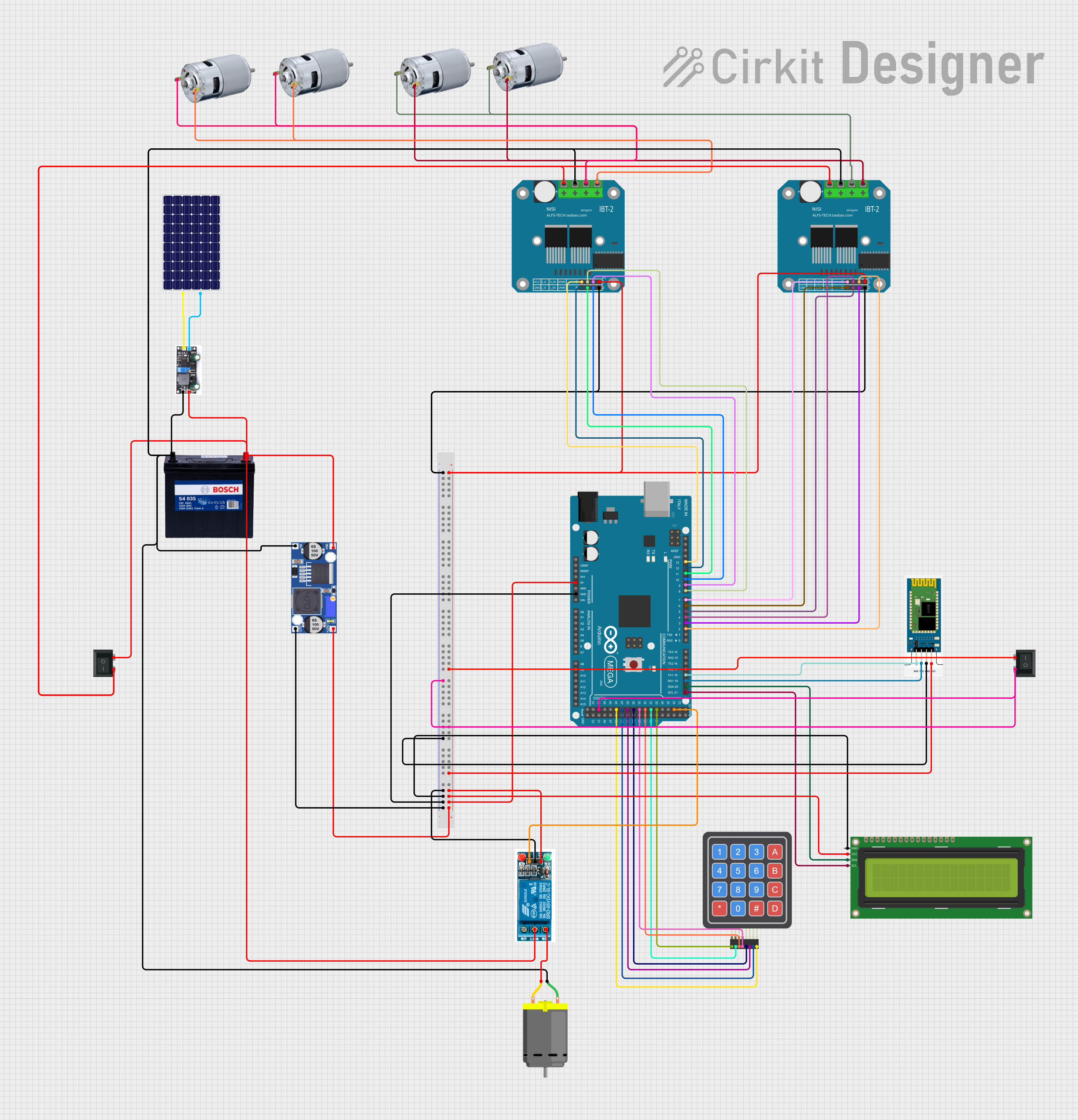
Example: Using Rush Blade F7 with Arduino UNO
Below is an example of how to control the Rush Blade F7 using an Arduino UNO:
// Example: Controlling Rush Blade F7 with Arduino UNO
// This code generates a PWM signal to control the Rush Blade F7 component.

const int pwmPin = 9; // PWM pin connected to the Rush Blade F7 PWM input

void setup() {
  pinMode(pwmPin, OUTPUT); // Set the PWM pin as an output
}

void loop() {
  analogWrite(pwmPin, 128); // Generate a 50% duty cycle PWM signal
  delay(1000); // Keep the signal for 1 second

  analogWrite(pwmPin, 255); // Generate a 100% duty cycle PWM signal
  delay(1000); // Keep the signal for 1 second
}
Note: Ensure the Arduino's PWM frequency matches the Rush Blade F7's requirements. You may need to adjust the PWM frequency using Arduino's timer settings.
Troubleshooting and FAQs
Common Issues and Solutions
Component Overheating
- Cause: Insufficient thermal dissipation.
- Solution: Ensure the thermal pad is properly soldered to a ground plane. Use a heat sink if necessary.
No Output Voltage
- Cause: EN pin not connected or set to low.
- Solution: Verify that the EN pin is connected to a logic high signal.
Erratic Switching Behavior
- Cause: Noisy or incorrect PWM signal.
- Solution: Use a clean PWM signal within the specified frequency range (up to 1 MHz).
Voltage Regulation Issues
- Cause: Improper feedback network.
- Solution: Check the voltage divider connected to the FB pin and ensure it is configured correctly.
FAQs
Q1: Can the Rush Blade F7 handle voltages above 24V?
A1: No, the maximum operating voltage is 24V. Exceeding this limit may damage the component.
Q2: Is the Rush Blade F7 suitable for battery-powered applications?
A2: Yes, its low resistance and high efficiency make it ideal for battery-powered circuits.
Q3: Can I leave the NC pins unconnected?
A3: Yes, the NC (No Connection) pins do not need to be connected to the circuit.
Q4: How do I calculate the required feedback resistor values?
A4: Use the formula ( V_{out} = V_{ref} \times (1 + \frac{R1}{R2}) ), where ( V_{ref} ) is the reference voltage of the component.
By following this documentation, users can effectively integrate the Rush Blade F7 into their designs and troubleshoot common issues.