How to Use 4×4 Keypad: Examples, Pinouts, and Specs
Introduction
A 4×4 keypad is an input device consisting of 16 buttons arranged in a 4x4 matrix. It is widely used in electronic projects and commercial products for entering numeric, alphabetic, and other symbol data. Common applications include security systems, telephone dial pads, and electronic door locks.
Explore Projects Built with 4×4 Keypad
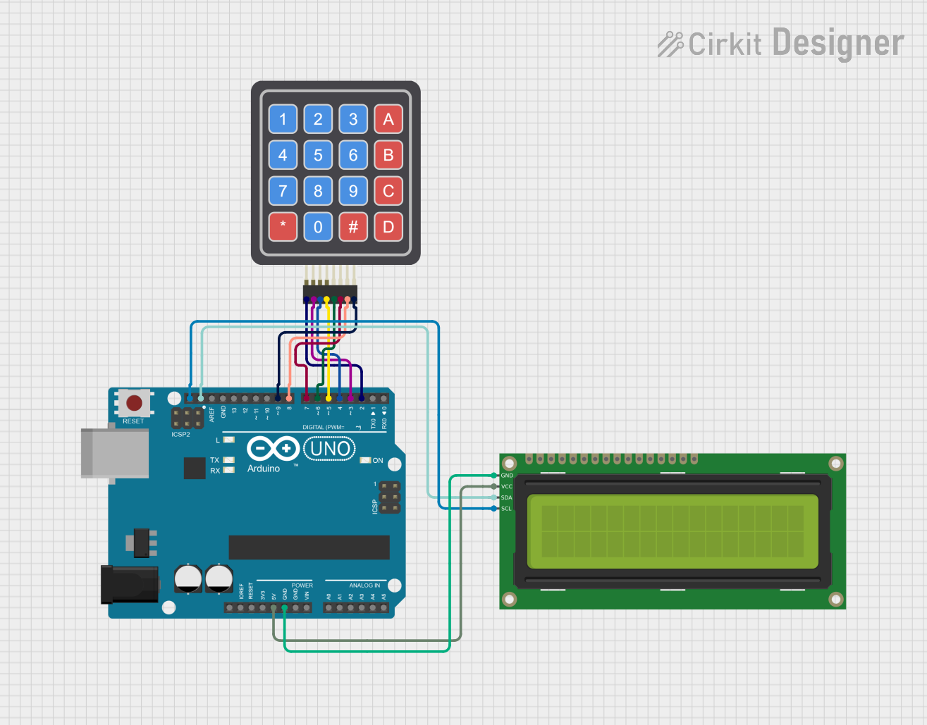

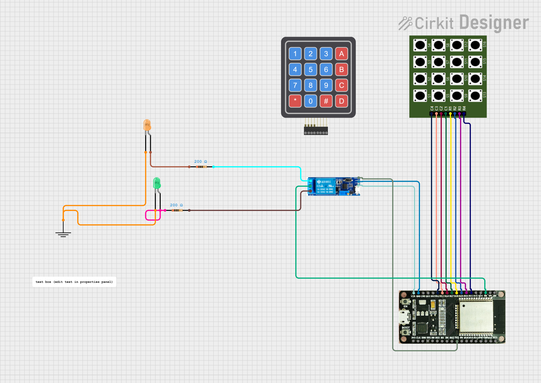
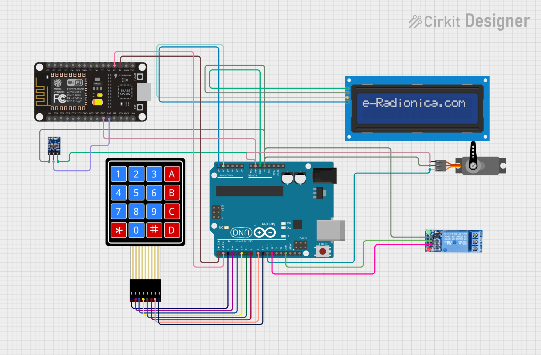
Explore Projects Built with 4×4 Keypad
Technical Specifications
Key Technical Details
- Operating Voltage: Typically 3.3V to 5V
- Interface: 8-pin matrix
- Contact Type: Momentary tactile
- Life Expectancy: Varies, often around 1 million presses per key
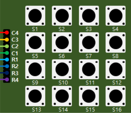
Pin Configuration and Descriptions
| Pin Number | Description |
|---|---|
| 1 | Row 1 |
| 2 | Row 2 |
| 3 | Row 3 |
| 4 | Row 4 |
| 5 | Column 1 |
| 6 | Column 2 |
| 7 | Column 3 |
| 8 | Column 4 |
Usage Instructions
Connecting to a Circuit
- Connect the row pins (1-4) to the digital input pins on your microcontroller.
- Connect the column pins (5-8) to the digital output pins on your microcontroller.
- Use pull-up or pull-down resistors as necessary to avoid floating pins.
Best Practices
- Debounce the keys in software to prevent multiple readings from a single press.
- Implement a scanning algorithm to detect which key is pressed.
- Avoid blocking code in the scanning loop to maintain responsive input detection.
Example Code for Arduino UNO
#include <Keypad.h>

const byte ROWS = 4; // Four rows
const byte COLS = 4; // Four columns

// Define the Keymap
char keys[ROWS][COLS] = {
  {'1','2','3','A'},
  {'4','5','6','B'},
  {'7','8','9','C'},
  {'*','0','#','D'}
};

// Connect keypad ROW0, ROW1, ROW2 and ROW3 to these Arduino pins.
byte rowPins[ROWS] = {9, 8, 7, 6};

// Connect keypad COL0, COL1, COL2 and COL3 to these Arduino pins.
byte colPins[COLS] = {5, 4, 3, 2};

// Create the Keypad
Keypad keypad = Keypad(makeKeymap(keys), rowPins, colPins, ROWS, COLS);

void setup() {
  Serial.begin(9600);
}

void loop() {
  char key = keypad.getKey();

  if (key) {
    Serial.println(key);
  }
}
Troubleshooting and FAQs
Common Issues
- Keys not responding: Ensure all connections are secure and the pins are correctly configured in your code.
- Multiple keypresses detected: Implement debouncing in your code to filter out noise.
- Incorrect characters displayed: Verify the keymap in your code matches the physical layout of the keypad.
Solutions and Tips
- Debouncing: Use software delays or libraries that handle debouncing to improve reliability.
- Scanning Algorithm: Ensure your scanning algorithm correctly identifies the active row and column.
- Wiring Check: Double-check the wiring against the pin configuration table to ensure accuracy.
FAQs
Q: Can I use the keypad with a 3.3V system? A: Yes, but ensure the keypad is rated for 3.3V operation.
Q: How can I clean the keypad? A: Use a soft, damp cloth. Avoid harsh chemicals and do not submerge the keypad.
Q: What is the maximum length of wire I can use to connect the keypad? A: It depends on the wire gauge and the environment, but keep it as short as possible to avoid signal degradation.
Remember to always power off your system before making any changes to the connections to prevent damage to the keypad or the microcontroller.