How to Use Single Channel Motor Driver: Examples, Pinouts, and Specs
Introduction
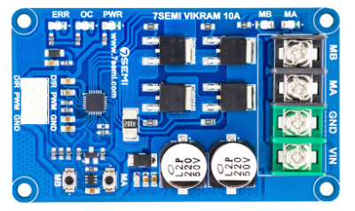
The Single Channel Motor Driver is a versatile electronic component designed to control the direction and speed of a single DC motor. By regulating the voltage and current supplied to the motor, this device enables precise motor control, making it an essential component in robotics, automation, and other motor-driven applications.
Explore Projects Built with Single Channel Motor Driver
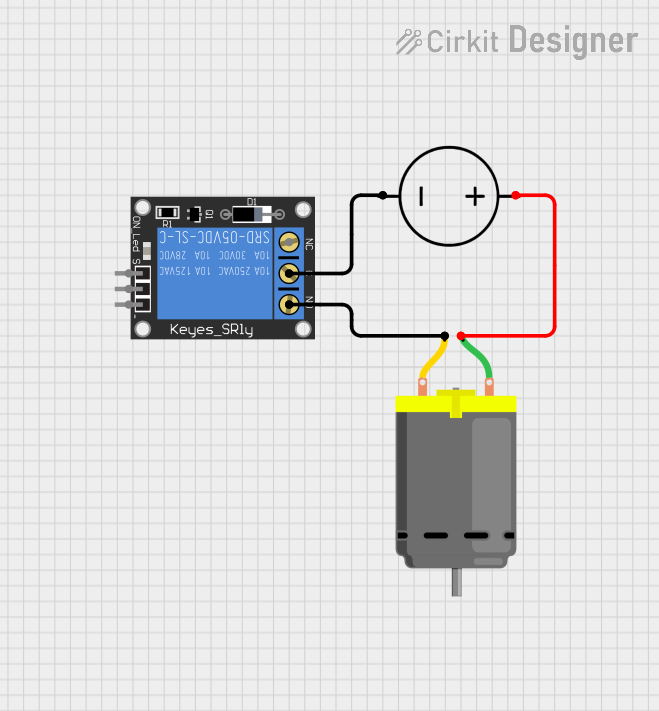


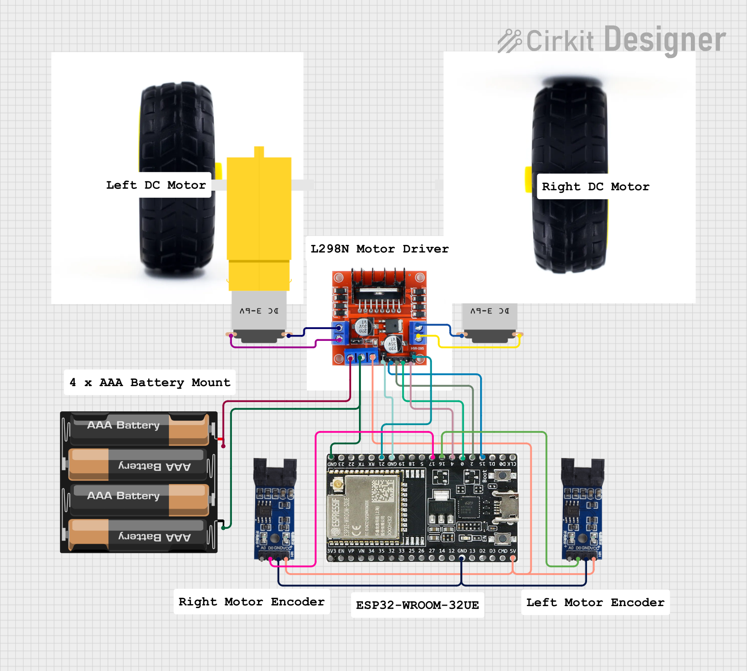
Explore Projects Built with Single Channel Motor Driver
Common Applications and Use Cases
- Robotics: Controlling wheels or robotic arms
- Automation systems: Conveyor belts, fans, or pumps
- Remote-controlled vehicles
- DIY electronics projects involving DC motors
- Educational projects for learning motor control
Technical Specifications
Below are the key technical details for a typical Single Channel Motor Driver. Specifications may vary slightly depending on the specific model.
General Specifications
- Operating Voltage: 5V to 30V (varies by model)
- Output Current: Up to 2A (continuous), 3A (peak)
- Control Logic Voltage: 3.3V or 5V (compatible with most microcontrollers)
- PWM Frequency: Up to 20 kHz
- Motor Type Supported: Brushed DC motors
- Protection Features: Overcurrent, thermal shutdown, and reverse polarity protection
Pin Configuration and Descriptions
The Single Channel Motor Driver typically has the following pin configuration:
| Pin Name | Description |
|---|---|
| VCC | Power supply input for the motor driver (5V to 30V). |
| GND | Ground connection. |
| IN1 | Input pin to control motor direction (logic HIGH or LOW). |
| IN2 | Input pin to control motor direction (logic HIGH or LOW). |
| EN (Enable) | PWM input to control motor speed (connect to a PWM-capable pin on a microcontroller). |
| OUT1 | Output pin connected to one terminal of the motor. |
| OUT2 | Output pin connected to the other terminal of the motor. |
Usage Instructions
How to Use the Component in a Circuit
- Power Supply: Connect the VCC pin to a power source that matches the motor's voltage requirements. Ensure the GND pin is connected to the ground of the power source and the microcontroller.
- Motor Connections: Connect the motor terminals to the OUT1 and OUT2 pins.
- Control Pins:
- Use the IN1 and IN2 pins to set the motor's direction:
- IN1 = HIGH, IN2 = LOW: Motor rotates in one direction.
- IN1 = LOW, IN2 = HIGH: Motor rotates in the opposite direction.
- IN1 = LOW, IN2 = LOW: Motor stops.
- Use the EN pin to control the motor's speed by providing a PWM signal from a microcontroller.
- Use the IN1 and IN2 pins to set the motor's direction:
- Microcontroller Integration: Connect the control pins (IN1, IN2, and EN) to the appropriate GPIO pins on your microcontroller.
Important Considerations and Best Practices
- Power Supply: Ensure the power supply voltage matches the motor's requirements and does not exceed the driver's maximum voltage rating.
- Heat Dissipation: If the motor driver gets hot during operation, consider adding a heat sink or improving ventilation.
- Current Limits: Do not exceed the driver's maximum current rating to avoid damage.
- Decoupling Capacitors: Add capacitors near the VCC and GND pins to reduce noise and voltage spikes.
Example: Using with Arduino UNO
Below is an example of how to control a DC motor using a Single Channel Motor Driver and an Arduino UNO.
// Define motor driver pins
const int IN1 = 9;  // Motor direction control pin 1
const int IN2 = 8;  // Motor direction control pin 2
const int EN = 10;  // Motor speed control (PWM) pin

void setup() {
  // Set motor driver pins as outputs
  pinMode(IN1, OUTPUT);
  pinMode(IN2, OUTPUT);
  pinMode(EN, OUTPUT);
}

void loop() {
  // Rotate motor in one direction at 50% speed
  digitalWrite(IN1, HIGH);  // Set IN1 HIGH
  digitalWrite(IN2, LOW);   // Set IN2 LOW
  analogWrite(EN, 128);     // Set speed to 50% (128 out of 255)
  delay(2000);              // Run for 2 seconds

  // Stop the motor
  digitalWrite(IN1, LOW);   // Set IN1 LOW
  digitalWrite(IN2, LOW);   // Set IN2 LOW
  analogWrite(EN, 0);       // Set speed to 0
  delay(1000);              // Wait for 1 second

  // Rotate motor in the opposite direction at full speed
  digitalWrite(IN1, LOW);   // Set IN1 LOW
  digitalWrite(IN2, HIGH);  // Set IN2 HIGH
  analogWrite(EN, 255);     // Set speed to 100% (255 out of 255)
  delay(2000);              // Run for 2 seconds

  // Stop the motor
  digitalWrite(IN1, LOW);   // Set IN1 LOW
  digitalWrite(IN2, LOW);   // Set IN2 LOW
  analogWrite(EN, 0);       // Set speed to 0
  delay(1000);              // Wait for 1 second
}
Troubleshooting and FAQs
Common Issues and Solutions
Motor Not Spinning:
- Check the power supply connections and ensure the voltage matches the motor's requirements.
- Verify that the IN1, IN2, and EN pins are receiving the correct signals from the microcontroller.
Motor Spins in the Wrong Direction:
- Swap the connections of the motor terminals to OUT1 and OUT2, or adjust the logic levels on IN1 and IN2.
Motor Driver Overheating:
- Ensure the motor's current draw does not exceed the driver's maximum current rating.
- Add a heat sink or improve ventilation around the driver.
PWM Signal Not Controlling Speed:
- Confirm that the EN pin is connected to a PWM-capable pin on the microcontroller.
- Check the PWM frequency and duty cycle settings in your code.
FAQs
Can I use this driver with a stepper motor? No, this driver is designed for brushed DC motors. Use a dedicated stepper motor driver for stepper motors.
What happens if I reverse the power supply polarity? Most motor drivers include reverse polarity protection, but it is best to double-check the datasheet for your specific model.
Can I control the motor without a microcontroller? Yes, you can use manual switches or a potentiometer to control the IN1, IN2, and EN pins, but a microcontroller provides more precise control.
This concludes the documentation for the Single Channel Motor Driver.