A rotary encoder is an electromechanical device that converts the angular position or motion of a shaft or axle into an analog or digital signal. It is widely used for position sensing, speed measurement, and control in various applications. Rotary encoders are commonly found in devices such as industrial machinery, robotics, CNC machines, and consumer electronics like volume knobs or scrolling wheels.
Rotary encoders are available in two main types:
Incremental Encoders: Provide relative position information and require an external reference point.
Absolute Encoders: Provide unique position information for every shaft position.
Explore Projects Built with Rotary Encoder
Use Cirkit Designer to design, explore, and prototype these projects online. Some projects support real-time simulation. Click "Open Project" to start designing instantly!
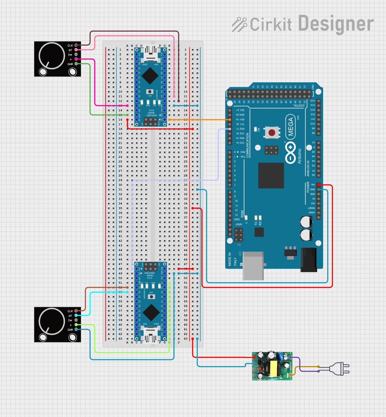
This circuit features an Arduino Mega 2560 and two Arduino Nano microcontrollers interfacing with two rotary encoders for input. The system is powered by an AC-DC PSU board converting 220V AC to 5V DC, and the microcontrollers communicate with each other via serial connections. The setup is designed for reading rotary encoder inputs and potentially processing or transmitting the data.
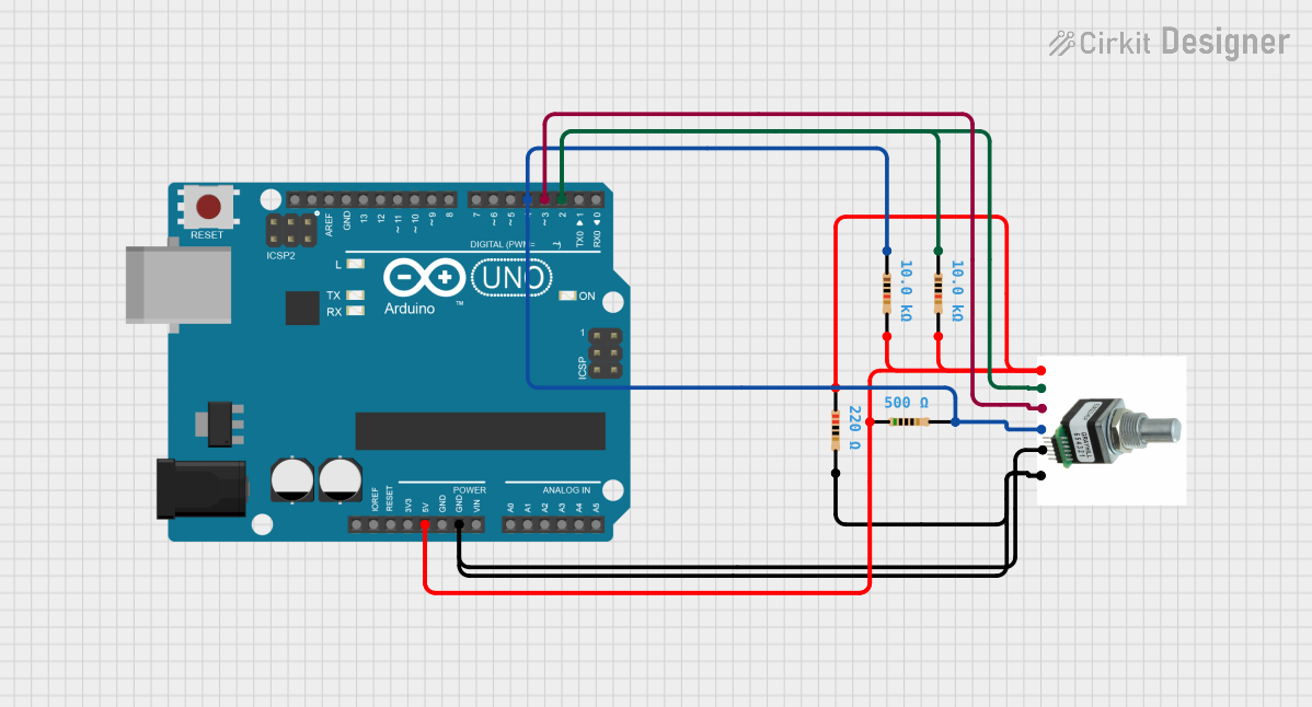
This circuit features a rotary encoder (로터리 엔코) interfaced with an Arduino UNO microcontroller. The encoder's outputs A and B are connected to digital pins D2 and D3 for rotation detection, while its push button is connected to D4, potentially for a user input function. The encoder, push button, and a switch are all debounced using resistors, and the microcontroller is set up to receive these signals for processing, although the provided code is empty and does not define specific behaviors.
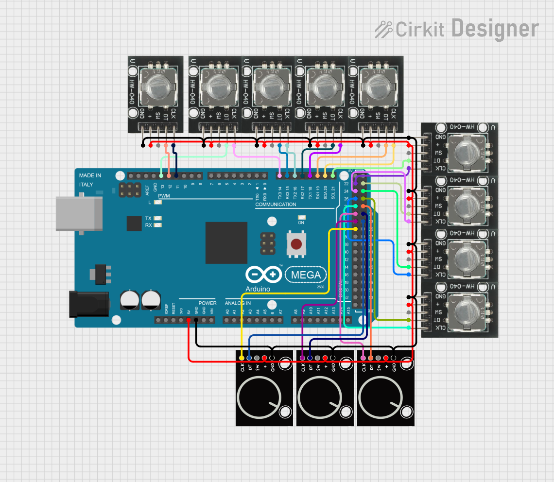
This circuit is designed to interface multiple rotary encoders with an Arduino Mega 2560 microcontroller. Each encoder's DT (data) and CLK (clock) pins are connected to specific digital input pins on the Arduino, allowing the microcontroller to read their rotational position changes. The encoders are powered by the Arduino's 5V output and share a common ground, suggesting that the circuit may be used for input devices in a user interface or control system.
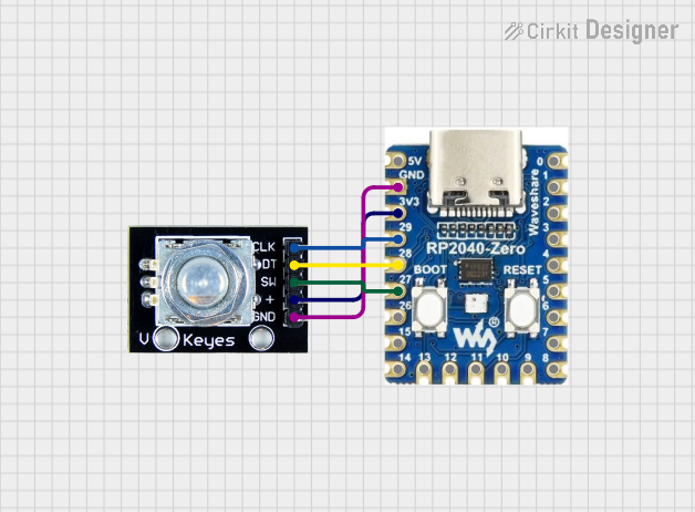
This circuit features an RP2040 Zero microcontroller interfaced with a rotary encoder. The encoder's clock, data, and switch pins are connected to the microcontroller's GPIO pins 29, 28, and 27, respectively, allowing the microcontroller to read the encoder's state and print it to the serial monitor.
Below are the general technical specifications for a typical rotary encoder:
Operating Voltage: 3.3V to 5V DC
Output Type: Digital (Quadrature signals: A and B channels)
Resolution: Typically 20 to 30 pulses per revolution (PPR) for standard encoders
Maximum Rotational Speed: Up to 10,000 RPM (varies by model)
Debouncing: May require external debouncing for stable signal output
Operating Temperature: -20°C to +85°C (varies by model)
Pin Configuration and Descriptions
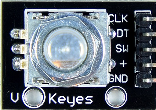
The rotary encoder typically has 5 pins. Below is the pinout and description:
Pin Name
Description
GND
Ground connection for the encoder.
VCC
Power supply input (3.3V or 5V, depending on the encoder model).
CLK (A)
Channel A output signal (used for detecting rotation direction and position).
DT (B)
Channel B output signal (used in conjunction with Channel A for quadrature).
SW
Push-button switch output (optional, available on some encoders).
Usage Instructions
How to Use the Rotary Encoder in a Circuit
Power the Encoder: Connect the VCC pin to a 3.3V or 5V power source and the GND pin to ground.
Connect Output Pins:
Connect the CLK (A) and DT (B) pins to digital input pins on your microcontroller.
If the encoder has a push-button switch (SW pin), connect it to another digital input pin.
Pull-up Resistors: Use pull-up resistors (typically 10kΩ) on the CLK, DT, and SW pins if they are not internally pulled up by the microcontroller.
Read Signals: Monitor the CLK and DT signals to determine the direction and position of rotation. The SW pin can be used to detect button presses.
Important Considerations and Best Practices
Debouncing: Rotary encoders may produce noisy signals due to mechanical contacts. Use software or hardware debouncing to ensure stable readings.
Signal Timing: Ensure your microcontroller can handle the signal frequency generated by the encoder, especially at high rotational speeds.
Direction Detection: The sequence of signals on the CLK and DT pins determines the direction of rotation:
If CLK leads DT, the rotation is clockwise.
If DT leads CLK, the rotation is counterclockwise.
Mounting: Securely mount the encoder to prevent mechanical vibrations or misalignment.
Example Code for Arduino UNO
Below is an example Arduino sketch to read a rotary encoder's position and direction:
// Rotary Encoder Pins
#define CLK 2  // Connect to the CLK (A) pin of the encoder
#define DT 3   // Connect to the DT (B) pin of the encoder
#define SW 4   // Connect to the SW (button) pin of the encoder (optional)

int counter = 0;          // Variable to store the encoder position
int currentStateCLK;      // Current state of the CLK pin
int lastStateCLK;         // Previous state of the CLK pin
bool buttonPressed = false; // Variable to track button press state

void setup() {
  pinMode(CLK, INPUT);
  pinMode(DT, INPUT);
  pinMode(SW, INPUT_PULLUP); // Enable internal pull-up resistor for the button
  Serial.begin(9600);

  // Read the initial state of the CLK pin
  lastStateCLK = digitalRead(CLK);
}

void loop() {
  // Read the current state of the CLK pin
  currentStateCLK = digitalRead(CLK);

  // If the state of CLK has changed, a rotation has occurred
  if (currentStateCLK != lastStateCLK) {
    // Check the state of the DT pin to determine rotation direction
    if (digitalRead(DT) != currentStateCLK) {
      counter++; // Clockwise rotation
    } else {
      counter--; // Counterclockwise rotation
    }

    // Print the current position to the Serial Monitor
    Serial.print("Position: ");
    Serial.println(counter);
  }

  // Update the last state of the CLK pin
  lastStateCLK = currentStateCLK;

  // Check if the button is pressed
  if (digitalRead(SW) == LOW) {
    if (!buttonPressed) {
      Serial.println("Button Pressed!");
      buttonPressed = true;
    }
  } else {
    buttonPressed = false;
  }
}
Notes:
Ensure the encoder is properly debounced in software or hardware to avoid erratic readings.
Use the Serial Monitor (set to 9600 baud) to view the encoder's position and button press status.
Troubleshooting and FAQs
Common Issues and Solutions
No Signal Detected:
Verify the power connections (VCC and GND).
Check the wiring of the CLK and DT pins to the microcontroller.
Ensure pull-up resistors are used if required.
Erratic or Noisy Readings:
Implement software debouncing in your code.
Use hardware debouncing with capacitors (e.g., 0.1µF) across the CLK and DT pins.
Incorrect Direction Detection:
Swap the CLK and DT connections to the microcontroller.
Verify the logic in your code for determining rotation direction.
Button Not Responding:
Check the SW pin connection and ensure it is configured as an input with a pull-up resistor.
Test the button with a multimeter to ensure it is functioning.
FAQs
Q: Can I use a rotary encoder with a 3.3V microcontroller?
A: Yes, most rotary encoders are compatible with 3.3V and 5V systems. Verify the operating voltage in the encoder's datasheet.
Q: How do I increase the resolution of my rotary encoder?
A: You can use software to detect both rising and falling edges of the CLK and DT signals, effectively doubling the resolution.
Q: Can I use multiple rotary encoders in the same circuit?
A: Yes, you can use multiple encoders by connecting each to separate digital input pins on your microcontroller.
Q: What is the difference between incremental and absolute encoders?
A: Incremental encoders provide relative position information, while absolute encoders provide a unique position value for every shaft position.
By following this documentation, you can effectively integrate and troubleshoot a rotary encoder in your projects.

 Open Project in Cirkit Designer