
How to Use Trafo 32V CT: Examples, Pinouts, and Specs
 Design with Trafo 32V CT in Cirkit Designer
Introduction
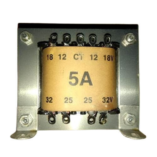
The Trafo 32V CT is a transformer with a center-tapped secondary winding, designed to provide a 32V AC output. This component is widely used in power supply applications, particularly in circuits requiring dual voltage outputs or rectification. Its center-tap configuration allows for flexible voltage configurations, making it suitable for both single and dual polarity power supplies.
Explore Projects Built with Trafo 32V CT
 Open Project in Cirkit Designer
 Open Project in Cirkit Designer
 Open Project in Cirkit Designer
 Open Project in Cirkit Designer
Explore Projects Built with Trafo 32V CT
Open Project in Cirkit DesignerOpen Project in Cirkit DesignerOpen Project in Cirkit DesignerOpen Project in Cirkit DesignerCommon Applications
- Power supply units for electronic devices
- Audio amplifiers
- Rectifier circuits for DC voltage generation
- Industrial control systems
- Battery charging circuits
Technical Specifications
The following table outlines the key technical details of the Trafo 32V CT:
| Parameter | Specification |
|---|---|
| Primary Voltage | 220V AC (typical) |
| Secondary Voltage | 32V AC (16V-0-16V with center tap) |
| Frequency | 50Hz / 60Hz |
| Power Rating | Varies (commonly 50VA to 200VA) |
| Winding Configuration | Center-tapped secondary winding |
| Insulation Class | Class B or higher |
| Efficiency | Typically 85% |
Pin Configuration
The Trafo 32V CT has the following pin configuration:
| Pin | Description |
|---|---|
| Pin 1 | Primary winding input (220V AC) |
| Pin 2 | Primary winding input (220V AC) |
| Pin 3 | Secondary winding (16V AC) |
| Pin 4 | Center tap (0V) |
| Pin 5 | Secondary winding (16V AC) |
Usage Instructions
How to Use the Trafo 32V CT in a Circuit
- Primary Connection: Connect the primary winding (Pin 1 and Pin 2) to the 220V AC mains supply. Ensure proper insulation and safety precautions when handling high voltage.
- Secondary Connection: Use the secondary winding (Pins 3, 4, and 5) to obtain the desired output:
- For 32V AC, connect across Pins 3 and 5.
- For dual 16V AC outputs, use Pins 3 and 4 for one output, and Pins 4 and 5 for the other.
- Rectification: To convert the AC output to DC, connect the secondary winding to a rectifier circuit (e.g., a bridge rectifier with smoothing capacitors).
- Load Connection: Connect the load to the rectified DC output or directly to the AC output, depending on the application.
Important Considerations
- Safety: Always handle the transformer with care, especially when working with the primary winding connected to mains voltage.
- Current Rating: Ensure the load does not exceed the transformer's current rating to avoid overheating or damage.
- Mounting: Securely mount the transformer to prevent vibrations or movement during operation.
- Fusing: Use appropriate fuses on both the primary and secondary sides for protection against overcurrent.
- Grounding: Properly ground the center tap (Pin 4) if required by the circuit design.
Example: Using the Trafo 32V CT with an Arduino UNO
To power an Arduino UNO using the Trafo 32V CT, you can use the following setup:
- Connect the secondary winding to a bridge rectifier circuit.
- Add a smoothing capacitor (e.g., 1000µF, 50V) to the rectified output.
- Use a voltage regulator (e.g., LM7805) to step down the voltage to 5V DC.
- Connect the regulated 5V output to the Arduino UNO's 5V pin and GND.
Here is an example Arduino code to blink an LED, assuming the transformer powers the Arduino:
// Blink an LED connected to pin 13 of the Arduino UNO
// Ensure the transformer powers the Arduino through a regulated 5V supply

void setup() {
  pinMode(13, OUTPUT); // Set pin 13 as an output
}

void loop() {
  digitalWrite(13, HIGH); // Turn the LED on
  delay(1000);            // Wait for 1 second
  digitalWrite(13, LOW);  // Turn the LED off
  delay(1000);            // Wait for 1 second
}
Troubleshooting and FAQs
Common Issues
No Output Voltage:
- Check the primary winding connections to ensure proper contact with the mains supply.
- Verify that the mains voltage is within the transformer's rated input range.
- Inspect the transformer for any visible damage or burnt windings.
Overheating:
- Ensure the load does not exceed the transformer's power rating.
- Check for short circuits on the secondary side.
- Verify proper ventilation around the transformer.
Voltage Drop Under Load:
- Confirm that the load current is within the transformer's rated capacity.
- Inspect the wiring for loose connections or high resistance.
Humming Noise:
- Ensure the transformer is securely mounted to reduce vibrations.
- Check for loose laminations in the transformer core.
FAQs
Q1: Can I use the Trafo 32V CT for DC applications?
A1: Yes, but you will need to use a rectifier circuit and smoothing capacitors to convert the AC output to DC.
Q2: What is the purpose of the center tap?
A2: The center tap allows for dual voltage outputs (e.g., ±16V AC) or a reference point for rectification circuits.
Q3: How do I calculate the current rating of the transformer?
A3: Divide the power rating (in VA) by the secondary voltage (e.g., for a 50VA transformer with 32V output, the current rating is 50VA ÷ 32V = 1.56A).
Q4: Can I use this transformer with a 110V AC mains supply?
A4: No, this transformer is designed for 220V AC input. Using it with 110V AC will result in reduced output voltage.