
How to Use Optocoupler: Examples, Pinouts, and Specs
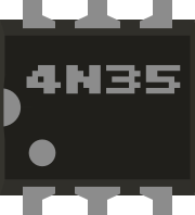
 Design with Optocoupler in Cirkit Designer
Introduction
An optocoupler is an electronic component that transfers electrical signals using light waves to provide electrical isolation between its input and output. It typically consists of a light-emitting diode (LED) and a photodetector, such as a phototransistor, photodiode, or photothyristor. This design allows signals to be transmitted without direct electrical connection, ensuring isolation and protection of sensitive circuits.
Explore Projects Built with Optocoupler
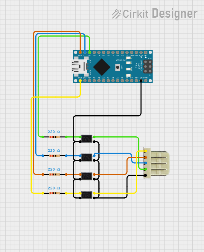 Open Project in Cirkit Designer
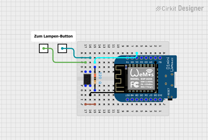 Open Project in Cirkit Designer
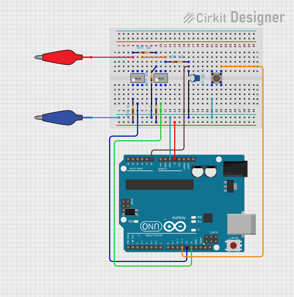 Open Project in Cirkit Designer
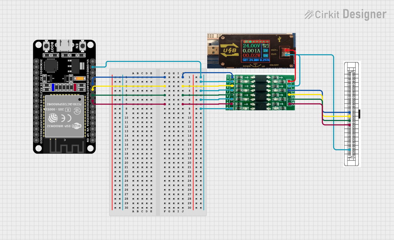 Open Project in Cirkit Designer
Explore Projects Built with Optocoupler
Open Project in Cirkit DesignerOpen Project in Cirkit DesignerOpen Project in Cirkit DesignerOpen Project in Cirkit DesignerCommon Applications and Use Cases
- Electrical Isolation: Protects low-voltage control circuits from high-voltage systems.
- Signal Transmission: Transfers signals between two circuits with different ground potentials.
- Noise Reduction: Reduces electrical noise in communication systems.
- Microcontroller Interfacing: Interfaces microcontrollers with high-power devices like relays or motors.
- Switching Applications: Used in solid-state relays and power control circuits.
Technical Specifications
Below are the general technical specifications for a typical optocoupler (e.g., 4N25 or PC817). Always refer to the datasheet of the specific model for precise details.
Key Technical Details
- Input Voltage (Forward Voltage): 1.2V to 1.4V (typical for the LED)
- Input Current (Forward Current): 10mA to 20mA (typical)
- Output Voltage (Collector-Emitter Voltage): Up to 35V (varies by model)
- Output Current (Collector Current): Up to 50mA (varies by model)
- Isolation Voltage: 2.5kV to 5kV (depends on the model)
- Response Time: 2µs to 20µs (varies by model and type of photodetector)
Pin Configuration and Descriptions
The pin configuration for a common 4-pin optocoupler (e.g., PC817) is as follows:
| Pin Number | Name | Description |
|---|---|---|
| 1 | Anode (LED+) | Positive terminal of the internal LED. |
| 2 | Cathode (LED-) | Negative terminal of the internal LED. |
| 3 | Emitter (Transistor) | Emitter terminal of the phototransistor. |
| 4 | Collector (Transistor) | Collector terminal of the phototransistor. |
Usage Instructions
How to Use the Component in a Circuit
Input Side (LED):
- Connect the anode (Pin 1) to the positive side of the input signal through a current-limiting resistor.
- Connect the cathode (Pin 2) to the ground of the input circuit.
- Calculate the resistor value using Ohm's Law:
[ R = \frac{V_{in} - V_f}{I_f} ]
Where (V_{in}) is the input voltage, (V_f) is the forward voltage of the LED, and (I_f) is the desired forward current.
Output Side (Phototransistor):
- Connect the collector (Pin 4) to the positive voltage supply through a pull-up resistor.
- Connect the emitter (Pin 3) to the ground of the output circuit.
- The phototransistor will conduct when the LED is illuminated, pulling the output low.
Important Considerations and Best Practices
- Isolation Voltage: Ensure the optocoupler's isolation voltage rating exceeds the voltage difference between the input and output circuits.
- Current Limiting: Always use a resistor to limit the current through the LED to prevent damage.
- Speed Requirements: For high-speed applications, choose an optocoupler with a fast response time.
- Temperature Range: Verify the operating temperature range of the optocoupler for your application.
Example: Interfacing an Optocoupler with Arduino UNO
Below is an example of using a PC817 optocoupler to control an LED with an Arduino UNO.
Circuit Connections
- Input Side:
- Connect Pin 1 (Anode) to Arduino digital pin 9 through a 220Ω resistor.
- Connect Pin 2 (Cathode) to Arduino GND.
- Output Side:
- Connect Pin 4 (Collector) to 5V through a 10kΩ pull-up resistor.
- Connect Pin 3 (Emitter) to GND.
- Connect an external LED with a 330Ω resistor between Pin 4 and GND.
Arduino Code
// Optocoupler Example with Arduino UNO
// This code toggles the optocoupler input to control an external LED.

const int optoInputPin = 9; // Arduino pin connected to optocoupler input

void setup() {
  pinMode(optoInputPin, OUTPUT); // Set pin as output
}

void loop() {
  digitalWrite(optoInputPin, HIGH); // Turn on optocoupler LED
  delay(1000); // Wait for 1 second
  digitalWrite(optoInputPin, LOW);  // Turn off optocoupler LED
  delay(1000); // Wait for 1 second
}
Troubleshooting and FAQs
Common Issues and Solutions
No Output Signal:
- Cause: Insufficient current through the LED.
- Solution: Check the input resistor value and ensure the LED current is within the specified range.
Output Signal Always High:
- Cause: Incorrect pull-up resistor value or damaged phototransistor.
- Solution: Verify the pull-up resistor value and replace the optocoupler if necessary.
Slow Response Time:
- Cause: Optocoupler not suitable for high-speed applications.
- Solution: Use a high-speed optocoupler designed for fast switching.
Overheating:
- Cause: Excessive current through the LED or phototransistor.
- Solution: Ensure proper current-limiting resistors are used on both sides.
FAQs
Q: Can an optocoupler handle AC signals?
A: Yes, but you may need additional circuitry, such as a bridge rectifier, to drive the LED with AC signals.Q: How do I choose the right optocoupler for my application?
A: Consider factors like isolation voltage, response time, input/output current, and voltage ratings.Q: Can I use an optocoupler for PWM signals?
A: Yes, but ensure the optocoupler's response time is fast enough to handle the PWM frequency.Q: What is the lifespan of an optocoupler?
A: Optocouplers have a long lifespan but may degrade over time due to LED aging. Check the datasheet for expected performance over time.