How to Use TP4057 1A: Examples, Pinouts, and Specs
Introduction
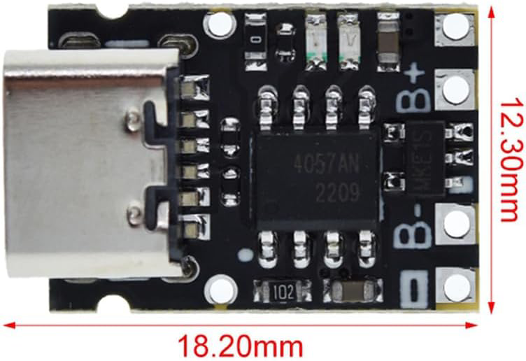
The TP4057 is a highly integrated lithium-ion battery charger IC designed to provide a constant current/constant voltage (CC/CV) charging profile. It is capable of charging single-cell lithium-ion batteries with a maximum charging current of 1A. The TP4057 is a compact and efficient solution for battery charging applications, requiring minimal external components. Its built-in safety features, such as thermal regulation and overvoltage protection, make it a reliable choice for portable electronics.
Explore Projects Built with TP4057 1A


Explore Projects Built with TP4057 1A
Common Applications
- Smartphones and tablets
- Wearable devices
- Power banks
- Portable medical equipment
- Wireless peripherals (e.g., headphones, mice, keyboards)
Technical Specifications
Key Technical Details
| Parameter | Value |
|---|---|
| Input Voltage Range | 4.0V to 8.0V |
| Charging Voltage | 4.2V ± 1% |
| Maximum Charging Current | 1A |
| Standby Current | < 25µA |
| Thermal Regulation | 120°C (typical) |
| Battery Overvoltage Limit | 4.35V |
| Operating Temperature Range | -40°C to +85°C |
| Package Type | SOT-23-5 |
Pin Configuration and Descriptions
The TP4057 is typically available in a 5-pin SOT-23 package. Below is the pinout and description:
| Pin Number | Pin Name | Description |
|---|---|---|
| 1 | BAT | Battery connection pin. Connect directly to the positive terminal of the battery. |
| 2 | GND | Ground pin. Connect to the system ground. |
| 3 | VCC | Input supply voltage. Connect to a DC source (4.0V to 8.0V). |
| 4 | PROG | Programming pin. Connect a resistor to set the charging current. |
| 5 | STAT | Status indicator pin. Open-drain output for charging status (e.g., LED). |
Usage Instructions
How to Use the TP4057 in a Circuit
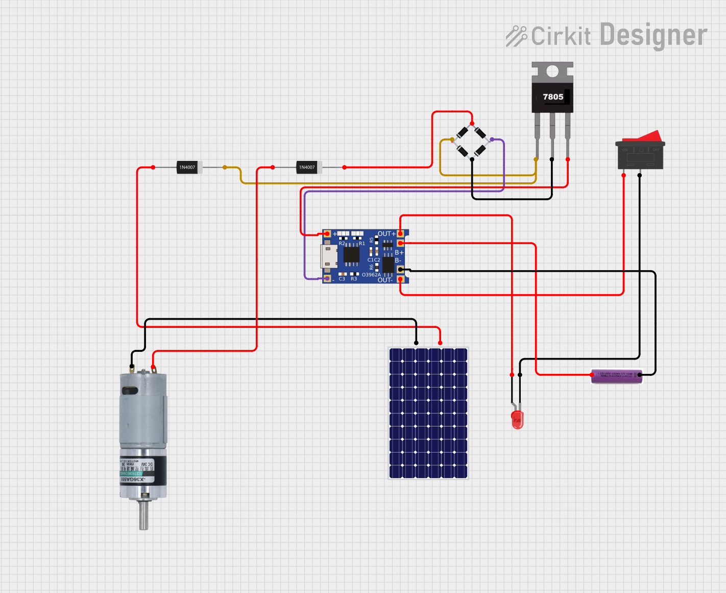
- Power Supply: Connect the VCC pin to a DC power source with a voltage between 4.0V and 8.0V. Ensure the power source can supply sufficient current for the charging process.
- Battery Connection: Connect the BAT pin directly to the positive terminal of the lithium-ion battery. The negative terminal of the battery should be connected to GND.
- Programming Charging Current: Use a resistor (RPROG) connected between the PROG pin and GND to set the charging current. The charging current (ICHG) can be calculated using the formula: [ I_{CHG} = \frac{1000}{R_{PROG}} ] For example, to set a charging current of 1A, use a 1kΩ resistor.
- Status Indicator: Connect an LED with a current-limiting resistor to the STAT pin to monitor the charging status:
- LED ON: Charging in progress.
- LED OFF: Charging complete or no battery connected.
Important Considerations and Best Practices
- Thermal Management: Ensure proper heat dissipation, as the TP4057 regulates its charging current to prevent overheating.
- Input Voltage: Avoid exceeding the maximum input voltage of 8.0V to prevent damage to the IC.
- Battery Safety: Use the TP4057 only with single-cell lithium-ion batteries. Do not use it for multi-cell configurations.
- Decoupling Capacitors: Place a 1µF ceramic capacitor close to the VCC pin to stabilize the input voltage and reduce noise.
Example: Using TP4057 with Arduino UNO
The TP4057 can be used in conjunction with an Arduino UNO to monitor the charging status. Below is an example code snippet:
// TP4057 Status Monitoring with Arduino UNO
// Connect the STAT pin of TP4057 to Arduino digital pin 2

const int statPin = 2; // TP4057 STAT pin connected to digital pin 2
const int ledPin = 13; // Onboard LED for status indication

void setup() {
  pinMode(statPin, INPUT); // Set STAT pin as input
  pinMode(ledPin, OUTPUT); // Set onboard LED as output
  Serial.begin(9600);      // Initialize serial communication
}

void loop() {
  int chargingStatus = digitalRead(statPin); // Read the STAT pin

  if (chargingStatus == LOW) {
    // Charging in progress (STAT pin LOW)
    digitalWrite(ledPin, HIGH); // Turn on onboard LED
    Serial.println("Battery is charging...");
  } else {
    // Charging complete or no battery connected (STAT pin HIGH)
    digitalWrite(ledPin, LOW); // Turn off onboard LED
    Serial.println("Charging complete or no battery connected.");
  }

  delay(1000); // Wait for 1 second before checking again
}
Troubleshooting and FAQs
Common Issues and Solutions
No Charging Current Detected
- Cause: Incorrect RPROG resistor value or poor connection.
- Solution: Verify the RPROG resistor value and ensure proper connections.
Overheating of the IC
- Cause: Insufficient heat dissipation or high ambient temperature.
- Solution: Improve thermal management by adding a heatsink or increasing airflow.
STAT Pin Not Functioning
- Cause: Faulty connection or damaged IC.
- Solution: Check the wiring and replace the IC if necessary.
Battery Not Charging
- Cause: Input voltage too low or battery voltage too high.
- Solution: Ensure the input voltage is within the 4.0V to 8.0V range and the battery voltage is below 4.2V.
FAQs
Q1: Can the TP4057 charge batteries with capacities greater than 1000mAh?
A1: Yes, the TP4057 can charge larger capacity batteries, but the charging current should not exceed 1A. Adjust the RPROG resistor accordingly.
Q2: Is it safe to leave the battery connected to the TP4057 after charging is complete?
A2: Yes, the TP4057 automatically terminates charging and enters a low-power standby mode when the battery is fully charged.
Q3: Can I use the TP4057 with a solar panel as the input source?
A3: Yes, as long as the solar panel provides a stable voltage within the 4.0V to 8.0V range. Use a capacitor to stabilize the input voltage.
Q4: What happens if the input voltage exceeds 8.0V?
A4: Exceeding 8.0V can damage the IC. Use a voltage regulator or zener diode to protect the TP4057.