How to Use nidec24h: Examples, Pinouts, and Specs
Introduction
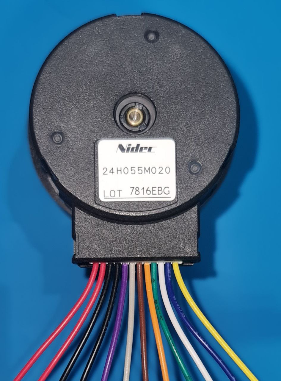
The Nidec 24H is a 24V DC brushless fan designed for high efficiency and reliability. It is widely used in cooling applications for electronic devices and systems, ensuring optimal thermal management in a variety of environments. Its brushless design enhances durability and reduces maintenance requirements, making it a preferred choice for industrial, commercial, and consumer electronics.
Explore Projects Built with nidec24h


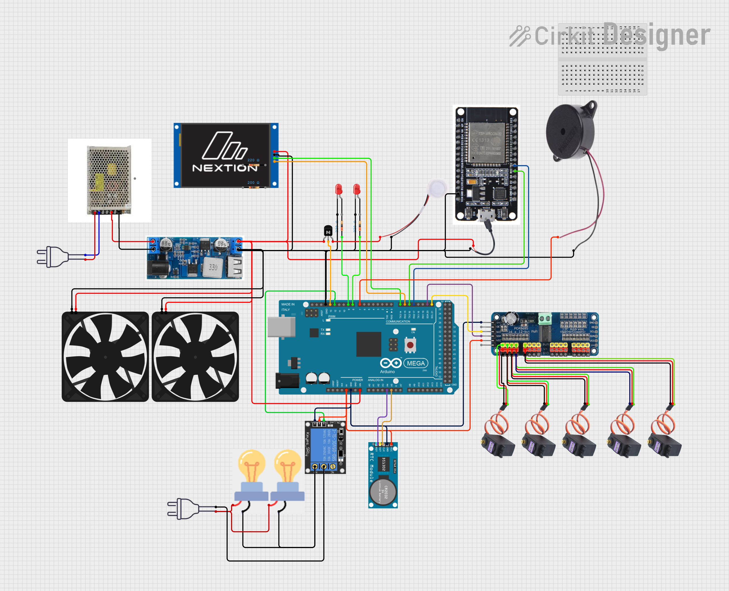
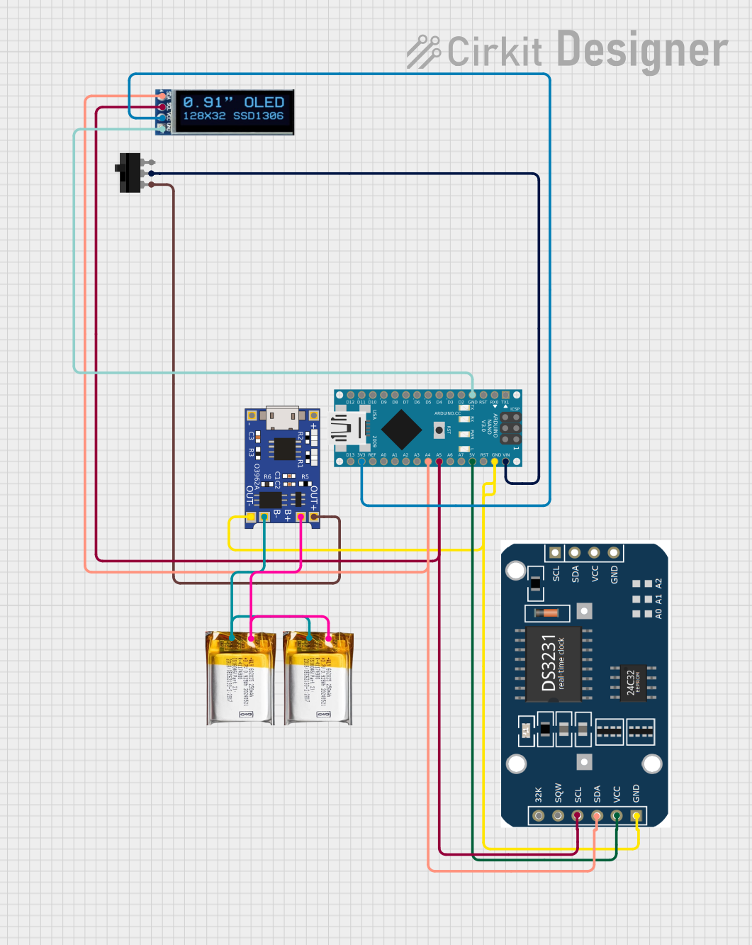
Explore Projects Built with nidec24h
Common Applications
- Cooling for power supplies, servers, and industrial equipment
- Thermal management in consumer electronics
- Ventilation in enclosures and cabinets
- Heat dissipation in renewable energy systems (e.g., solar inverters)
Technical Specifications
Key Specifications
| Parameter | Value |
|---|---|
| Operating Voltage | 24V DC |
| Operating Voltage Range | 18V - 26V DC |
| Current Consumption | 0.15A (typical) |
| Power Consumption | 3.6W (typical) |
| Speed | 3000 RPM (±10%) |
| Airflow | 50 CFM (Cubic Feet/Minute) |
| Noise Level | 28 dBA |
| Bearing Type | Ball Bearing |
| Dimensions | 80mm x 80mm x 25mm |
| Weight | 120g |
| Connector Type | 3-pin (Power, Ground, Tachometer) |
Pin Configuration
| Pin Number | Name | Description |
|---|---|---|
| 1 | Power (V+) | Connect to 24V DC power supply |
| 2 | Ground (GND) | Connect to circuit ground |
| 3 | Tachometer | Outputs a pulse signal for speed monitoring |
Usage Instructions
How to Use the Nidec 24H in a Circuit
- Power Connection: Connect the Power (V+) pin to a 24V DC power source. Ensure the power supply can provide at least 0.2A to account for startup current.
- Ground Connection: Connect the Ground (GND) pin to the circuit ground.
- Tachometer Signal (Optional): If speed monitoring is required, connect the Tachometer pin to a microcontroller or monitoring circuit. The tachometer outputs a square wave signal proportional to the fan speed.
Important Considerations
- Voltage Range: Ensure the input voltage remains within the specified range (18V - 26V DC) to avoid damage.
- Mounting: Secure the fan using screws or brackets to minimize vibration and noise.
- Airflow Direction: Check the airflow direction indicated on the fan housing before installation.
- Noise Reduction: Use rubber grommets or vibration dampeners to reduce noise in sensitive applications.
Example: Connecting to an Arduino UNO
The Nidec 24H can be connected to an Arduino UNO for speed monitoring using the Tachometer pin. Below is an example code snippet to read the fan speed:
// Arduino code to monitor the speed of the Nidec 24H fan
// The Tachometer pin is connected to Arduino digital pin 2

const int tachPin = 2; // Tachometer signal pin
volatile int pulseCount = 0; // Variable to store pulse count

void setup() {
  pinMode(tachPin, INPUT_PULLUP); // Set tachPin as input with pull-up resistor
  attachInterrupt(digitalPinToInterrupt(tachPin), countPulse, FALLING);
  Serial.begin(9600); // Initialize serial communication
}

void loop() {
  delay(1000); // Wait for 1 second
  int rpm = (pulseCount / 2) * 60; // Calculate RPM (2 pulses per revolution)
  Serial.print("Fan Speed: ");
  Serial.print(rpm);
  Serial.println(" RPM");
  pulseCount = 0; // Reset pulse count for the next measurement
}

void countPulse() {
  pulseCount++; // Increment pulse count on each falling edge
}
Notes:
- The Tachometer pin outputs two pulses per revolution. The code calculates RPM accordingly.
- Use a pull-up resistor if the Arduino's internal pull-up is insufficient for stable readings.
Troubleshooting and FAQs
Common Issues and Solutions
Fan Does Not Spin
- Cause: Insufficient power supply or incorrect wiring.
- Solution: Verify the power supply voltage and current. Check the wiring connections.
Excessive Noise or Vibration
- Cause: Loose mounting or misalignment.
- Solution: Secure the fan properly using screws or vibration dampeners.
Tachometer Signal Not Detected
- Cause: Incorrect connection or incompatible microcontroller pin.
- Solution: Ensure the Tachometer pin is connected to a digital input pin with interrupt capability. Verify the pull-up resistor.
Fan Speed Fluctuates
- Cause: Unstable power supply or environmental factors.
- Solution: Use a regulated power supply and ensure proper airflow around the fan.
FAQs
Can the Nidec 24H operate at 12V?
- No, the fan requires a minimum of 18V for proper operation.
What is the lifespan of the Nidec 24H?
- The fan has an estimated lifespan of 50,000 hours at 25°C.
Can the fan be controlled using PWM?
- No, the Nidec 24H does not support PWM speed control. Use a voltage regulator for speed adjustment.
Is the fan waterproof?
- No, the Nidec 24H is not waterproof. Avoid exposure to liquids or high humidity environments.