How to Use RGB Modul : Examples, Pinouts, and Specs
Introduction
An RGB module is a versatile electronic component that integrates red, green, and blue LEDs into a single package. By adjusting the intensity of each LED, users can create a wide spectrum of colors. RGB modules are widely used in applications such as decorative lighting, displays, mood lighting, and DIY electronics projects. They are often controlled using microcontrollers like Arduino, Raspberry Pi, or other programmable devices, making them a popular choice for hobbyists and professionals alike.
Explore Projects Built with RGB Modul
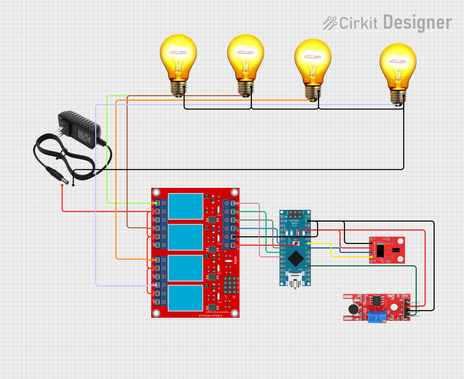
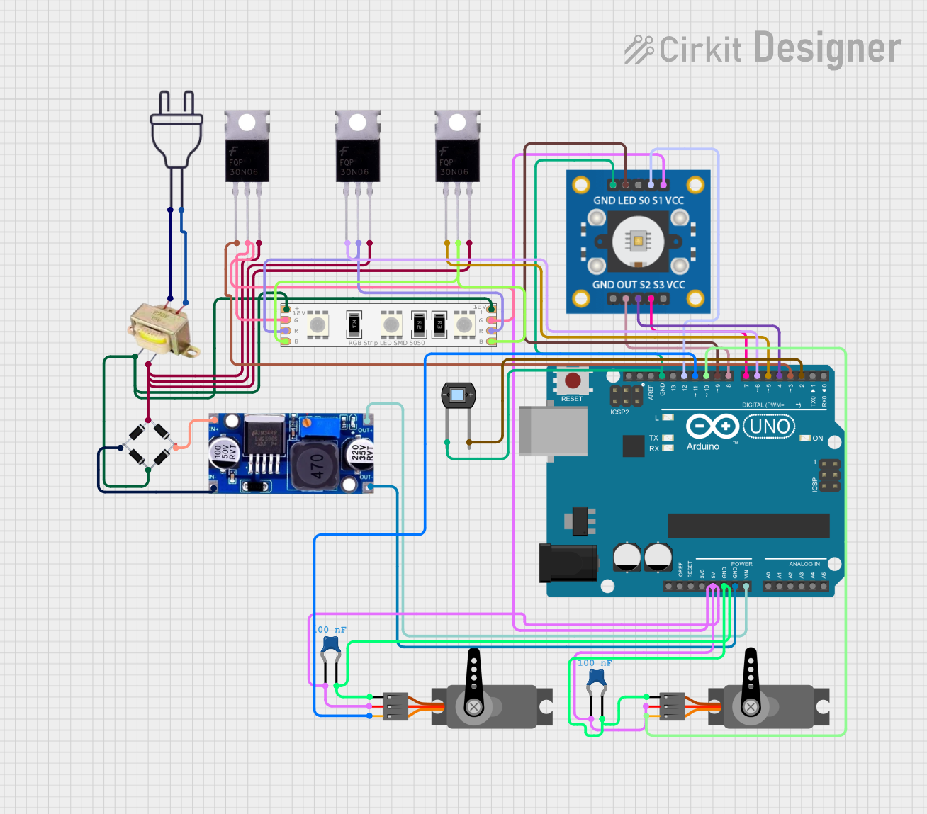
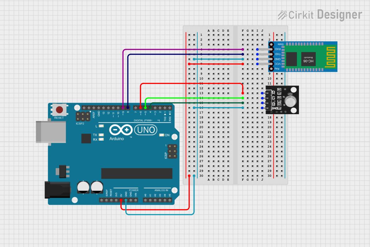
Explore Projects Built with RGB Modul
Technical Specifications
- Operating Voltage: Typically 3.3V to 5V (check specific module datasheet)
- Current Consumption: ~20mA per LED channel (red, green, blue)
- LED Type: Common cathode or common anode (varies by module)
- Control Method: PWM (Pulse Width Modulation) for color mixing
- Dimensions: Varies by module, typically compact for easy integration
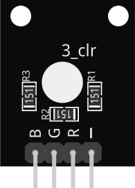
Pin Configuration and Descriptions
Below is a typical pinout for a 4-pin RGB module (common cathode type):
| Pin | Name | Description |
|---|---|---|
| 1 | R (Red) | Controls the red LED. Connect to a PWM pin on the microcontroller via a resistor. |
| 2 | G (Green) | Controls the green LED. Connect to a PWM pin on the microcontroller via a resistor. |
| 3 | B (Blue) | Controls the blue LED. Connect to a PWM pin on the microcontroller via a resistor. |
| 4 | Cathode (GND) | Common cathode pin. Connect to ground (GND) of the power supply or microcontroller. |
Note: For common anode modules, the anode pin is connected to the positive voltage supply, and the R, G, and B pins are connected to ground via resistors.
Usage Instructions
How to Use the RGB Module in a Circuit
Connect the Pins:
- Identify the type of RGB module (common cathode or common anode).
- For a common cathode module:
- Connect the cathode pin to the ground (GND) of your power supply or microcontroller.
- Connect the R, G, and B pins to PWM-capable pins on your microcontroller through current-limiting resistors (typically 220Ω to 330Ω).
- For a common anode module:
- Connect the anode pin to the positive voltage supply (e.g., 5V).
- Connect the R, G, and B pins to ground via current-limiting resistors.
Control the Colors:
- Use PWM signals to control the brightness of each LED channel (R, G, B).
- By varying the duty cycle of the PWM signals, you can mix colors to achieve the desired output.
Power Considerations:
- Ensure the power supply can handle the current requirements of the module.
- Use appropriate resistors to prevent overdriving the LEDs.
Example Code for Arduino UNO
Below is an example of how to control an RGB module using an Arduino UNO:
// Define the PWM pins connected to the RGB module
const int redPin = 9;   // Red LED connected to pin 9
const int greenPin = 10; // Green LED connected to pin 10
const int bluePin = 11;  // Blue LED connected to pin 11

void setup() {
  // Set the RGB pins as output
  pinMode(redPin, OUTPUT);
  pinMode(greenPin, OUTPUT);
  pinMode(bluePin, OUTPUT);
}

void loop() {
  // Example: Create a purple color by mixing red and blue
  analogWrite(redPin, 128);  // Set red LED to 50% brightness
  analogWrite(greenPin, 0);  // Turn off green LED
  analogWrite(bluePin, 128); // Set blue LED to 50% brightness
  delay(1000);               // Wait for 1 second

  // Example: Create a cyan color by mixing green and blue
  analogWrite(redPin, 0);    // Turn off red LED
  analogWrite(greenPin, 128); // Set green LED to 50% brightness
  analogWrite(bluePin, 128); // Set blue LED to 50% brightness
  delay(1000);               // Wait for 1 second

  // Example: Turn off all LEDs
  analogWrite(redPin, 0);
  analogWrite(greenPin, 0);
  analogWrite(bluePin, 0);
  delay(1000);               // Wait for 1 second
}
Tip: Adjust the
analogWritevalues (0-255) to experiment with different colors and brightness levels.
Important Considerations and Best Practices
- Always use current-limiting resistors to protect the LEDs from excessive current.
- Verify the type of RGB module (common cathode or common anode) before connecting it to your circuit.
- Use a stable power supply to avoid flickering or inconsistent color output.
- For smoother color transitions, consider using libraries like
FastLEDorAdafruit_NeoPixel(if using addressable RGB modules).
Troubleshooting and FAQs
Common Issues and Solutions
No Light Output:
- Check the connections and ensure the module is powered correctly.
- Verify that the resistors are not too large, which could limit current excessively.
Incorrect Colors:
- Ensure the correct pins are connected to the corresponding R, G, and B channels.
- Verify the type of module (common cathode or common anode) and adjust the wiring accordingly.
Flickering LEDs:
- Check for loose connections or unstable power supply.
- Ensure the PWM frequency is appropriate for the LEDs (typically above 500Hz).
Overheating:
- Ensure the resistors are properly rated to limit current.
- Avoid driving the LEDs at maximum brightness for extended periods.
FAQs
Q: Can I use the RGB module with a 12V power supply?
A: Most RGB modules are designed for 3.3V to 5V operation. Using a 12V supply may damage the LEDs. Use a step-down regulator or a module rated for 12V if needed.
Q: How do I create a specific color?
A: Use the RGB color model to determine the intensity of each channel. For example, to create yellow, mix red and green at equal intensities (e.g., analogWrite(redPin, 255); analogWrite(greenPin, 255); analogWrite(bluePin, 0);).
Q: Can I control the RGB module without a microcontroller?
A: Yes, you can use potentiometers to manually adjust the brightness of each channel, but this limits automation and precision.
By following this documentation, you can effectively integrate and control an RGB module in your projects!