
How to Use Adafruit ADS1115 16Bit I2C ADC: Examples, Pinouts, and Specs
 Design with Adafruit ADS1115 16Bit I2C ADC in Cirkit Designer
Introduction
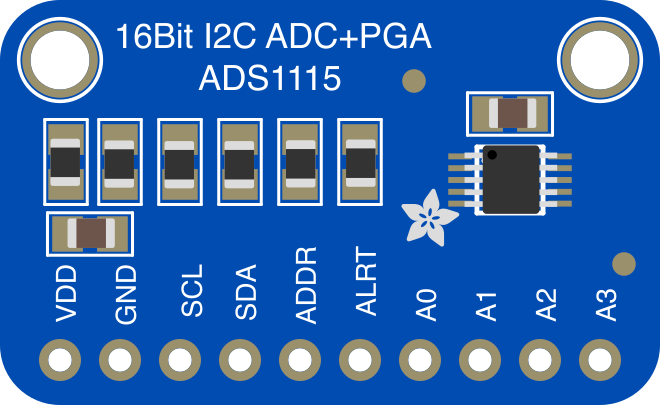
The Adafruit ADS1115 (Part ID: 1085) is a precision analog-to-digital converter (ADC) that offers 16-bit resolution. It is designed to measure analog signals with high accuracy and communicates via the I2C protocol, making it an excellent choice for applications requiring precise analog measurements. The ADS1115 features a programmable gain amplifier (PGA), allowing it to handle a wide range of input voltages.
Explore Projects Built with Adafruit ADS1115 16Bit I2C ADC
 Open Project in Cirkit Designer
 Open Project in Cirkit Designer
 Open Project in Cirkit Designer
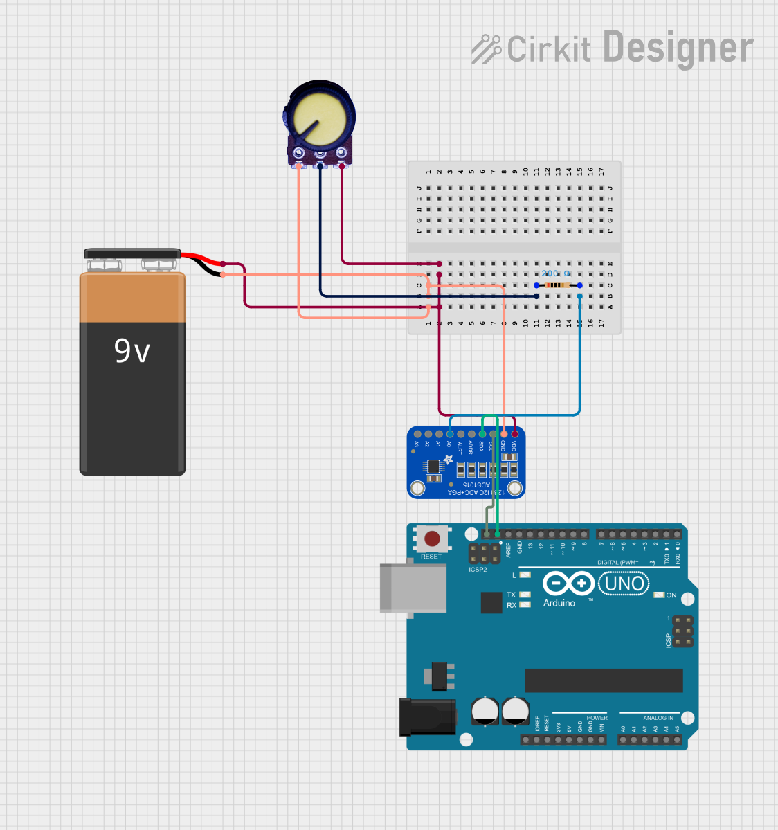 Open Project in Cirkit Designer
Explore Projects Built with Adafruit ADS1115 16Bit I2C ADC
Open Project in Cirkit DesignerOpen Project in Cirkit DesignerOpen Project in Cirkit DesignerOpen Project in Cirkit DesignerCommon Applications and Use Cases
- Sensor data acquisition (e.g., temperature, pressure, light sensors)
- Battery monitoring and power management
- Data logging systems
- Industrial automation and control
- Audio signal processing
Technical Specifications
The following table outlines the key technical details of the Adafruit ADS1115:
| Parameter | Value |
|---|---|
| Resolution | 16-bit |
| Input Channels | 4 (single-ended) or 2 (differential) |
| Input Voltage Range | 0 to VDD (single-ended) |
| Programmable Gain Amplifier | ±0.256V to ±6.144V (configurable) |
| Communication Interface | I2C |
| I2C Address | 0x48 (default), configurable to 0x49, 0x4A, or 0x4B |
| Supply Voltage (VDD) | 2.0V to 5.5V |
| Operating Current | 150 µA (typical) |
| Data Rate | Programmable: 8 SPS to 860 SPS |
| Operating Temperature Range | -40°C to +125°C |
Pin Configuration and Descriptions
The ADS1115 has six pins, as described in the table below:
| Pin | Name | Description |
|---|---|---|
| 1 | VDD | Power supply input (2.0V to 5.5V). |
| 2 | GND | Ground connection. |
| 3 | SCL | I2C clock line. Connect to the SCL pin of the microcontroller. |
| 4 | SDA | I2C data line. Connect to the SDA pin of the microcontroller. |
| 5 | ADDR | I2C address selection. Connect to GND, VDD, SDA, or SCL to set the I2C address. |
| 6 | ALERT/RDY | Configurable pin for alert or ready signal. |
Usage Instructions
How to Use the ADS1115 in a Circuit
- Power the ADS1115: Connect the VDD pin to a 2.0V–5.5V power source and the GND pin to ground.
- Connect I2C Lines: Connect the SCL and SDA pins to the corresponding I2C pins on your microcontroller. Use pull-up resistors (typically 4.7kΩ) on the SCL and SDA lines if not already present.
- Set the I2C Address: Use the ADDR pin to configure the I2C address:
- Connect to GND for 0x48 (default).
- Connect to VDD for 0x49.
- Connect to SDA for 0x4A.
- Connect to SCL for 0x4B.
- Connect Analog Inputs: Attach the analog signals to the AIN0–AIN3 pins. Configure the ADS1115 for single-ended or differential mode as needed.
- Optional ALERT/RDY Pin: Use this pin for interrupt-driven applications or to monitor conversion readiness.
Important Considerations and Best Practices
- Ensure the input voltage does not exceed the configured PGA range or the supply voltage (VDD).
- Use decoupling capacitors (e.g., 0.1µF) near the VDD pin to reduce noise.
- For accurate measurements, avoid long wires for analog inputs to minimize noise and interference.
- Configure the data rate and PGA settings based on your application's requirements.
Example Code for Arduino UNO
Below is an example of how to use the ADS1115 with an Arduino UNO to read a single-ended analog input:
#include <Wire.h>
#include <Adafruit_ADS1X15.h>

// Create an instance of the ADS1115 ADC
Adafruit_ADS1115 ads;

void setup() {
  Serial.begin(9600); // Initialize serial communication at 9600 baud
  if (!ads.begin()) {
    Serial.println("Failed to initialize ADS1115. Check connections!");
    while (1); // Halt execution if initialization fails
  }
  Serial.println("ADS1115 initialized successfully!");
}

void loop() {
  // Read a single-ended input from channel 0
  int16_t adcValue = ads.readADC_SingleEnded(0);

  // Convert the ADC value to voltage (assuming default gain ±6.144V)
  float voltage = adcValue * 0.1875 / 1000; // 0.1875mV per bit

  // Print the ADC value and corresponding voltage
  Serial.print("ADC Value: ");
  Serial.print(adcValue);
  Serial.print(" | Voltage: ");
  Serial.print(voltage, 4); // Print voltage with 4 decimal places
  Serial.println(" V");

  delay(1000); // Wait for 1 second before the next reading
}
Troubleshooting and FAQs
Common Issues and Solutions
ADS1115 Not Detected on I2C Bus
- Cause: Incorrect wiring or I2C address configuration.
- Solution: Verify the connections to the SDA and SCL pins. Ensure the ADDR pin is set correctly.
Inaccurate Readings
- Cause: Input voltage exceeds the configured PGA range or supply voltage.
- Solution: Check the input voltage and adjust the PGA settings accordingly.
No Output or Communication Failure
- Cause: Missing pull-up resistors on the I2C lines.
- Solution: Add 4.7kΩ pull-up resistors to the SDA and SCL lines.
High Noise in Measurements
- Cause: Long wires or noisy environment.
- Solution: Use shorter wires and add decoupling capacitors near the VDD pin.
FAQs
Q: Can the ADS1115 measure negative voltages?
A: Yes, but only in differential mode. The negative voltage must not exceed the PGA range or the supply voltage.
Q: What is the maximum sampling rate of the ADS1115?
A: The maximum sampling rate is 860 samples per second (SPS).
Q: Can I use multiple ADS1115 modules on the same I2C bus?
A: Yes, up to four ADS1115 modules can be used by configuring different I2C addresses using the ADDR pin.
Q: Is the ADS1115 compatible with 3.3V and 5V logic levels?
A: Yes, the ADS1115 supports both 3.3V and 5V logic levels, as long as the supply voltage (VDD) matches the logic level.
This concludes the documentation for the Adafruit ADS1115 16Bit I2C ADC.