How to Use RYLS135 USB to UART TTL Converter: Examples, Pinouts, and Specs
Introduction
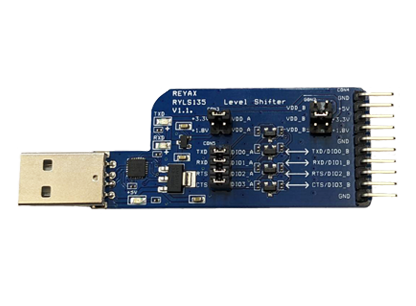
The RYLS135 USB to UART TTL Converter by REYAX is a compact and reliable device designed to bridge USB signals with UART TTL signals. It enables seamless communication between USB-enabled devices, such as computers, and microcontrollers or other serial devices. This converter is widely used in prototyping, debugging, and interfacing applications where serial communication is required.
Explore Projects Built with RYLS135 USB to UART TTL Converter


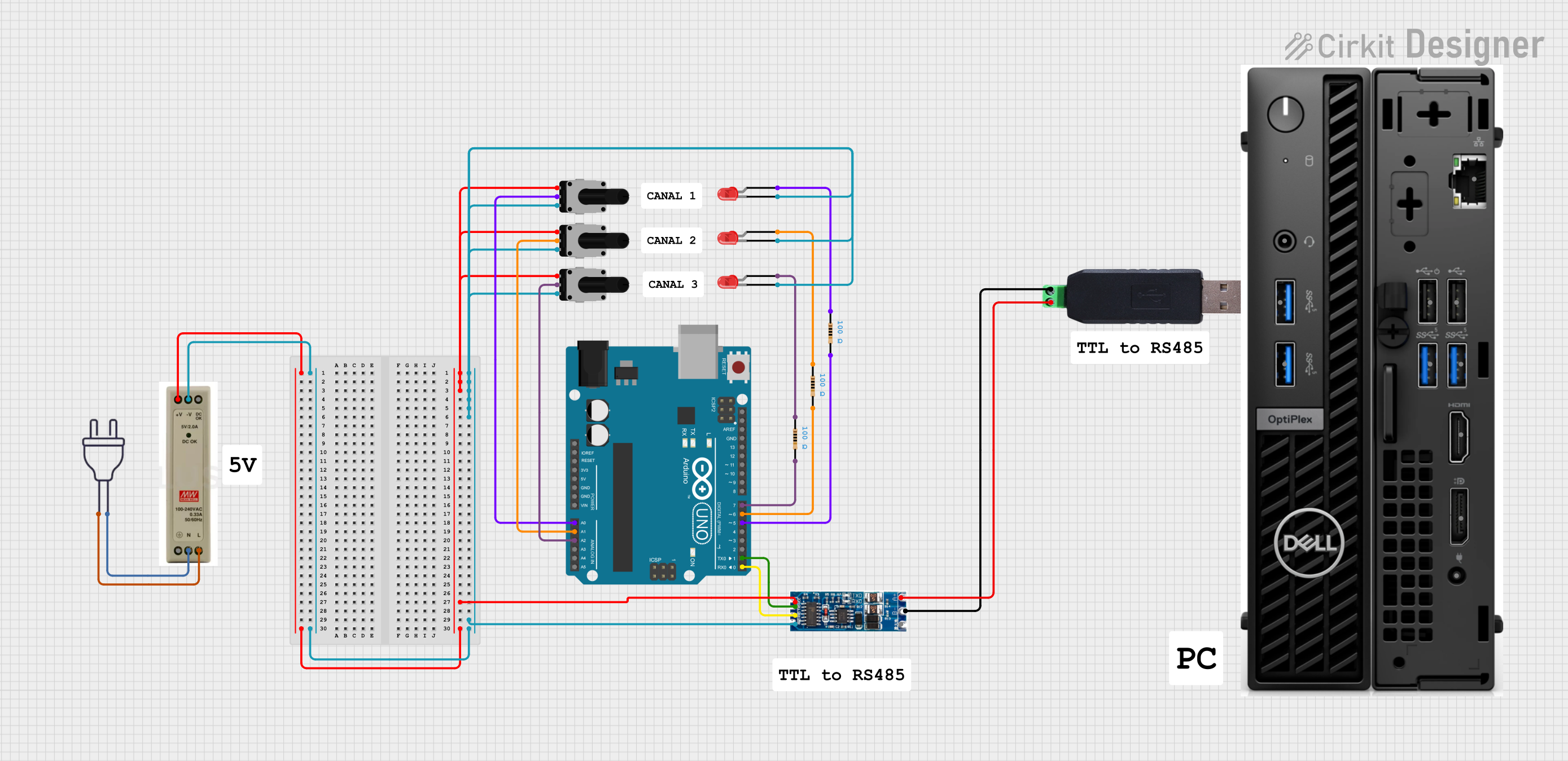
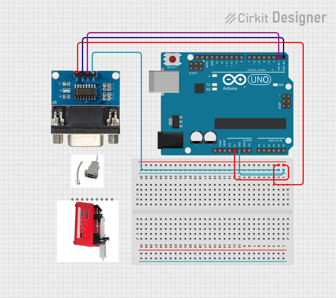
Explore Projects Built with RYLS135 USB to UART TTL Converter
Common Applications and Use Cases
- Programming and debugging microcontrollers (e.g., Arduino, ESP32, STM32)
- Interfacing with serial devices such as GPS modules, GSM modules, and sensors
- Data logging and monitoring via USB
- Serial communication testing and diagnostics
- USB-to-serial communication for legacy systems
Technical Specifications
The RYLS135 is designed to provide reliable and efficient USB-to-TTL conversion. Below are its key technical details:
General Specifications
| Parameter | Value |
|---|---|
| Manufacturer | REYAX |
| Part ID | RYLS135 |
| USB Interface | USB 2.0 (Type-A or Type-C) |
| UART Logic Level | TTL (3.3V or 5V selectable) |
| Baud Rate Support | 300 bps to 3 Mbps |
| Operating Voltage | 5V (via USB) |
| Power Consumption | < 50 mA |
| Operating Temperature | -40°C to 85°C |
| Dimensions | 40mm x 15mm x 5mm |
Pin Configuration and Descriptions
The RYLS135 features a 6-pin header for UART communication. Below is the pinout:
| Pin Number | Pin Name | Description |
|---|---|---|
| 1 | GND | Ground |
| 2 | TXD | Transmit Data (UART output from RYLS135) |
| 3 | RXD | Receive Data (UART input to RYLS135) |
| 4 | VCC | Power output (3.3V or 5V, selectable via jumper) |
| 5 | RTS | Request to Send (optional flow control) |
| 6 | CTS | Clear to Send (optional flow control) |
Jumper Settings
The RYLS135 includes a jumper to select the UART logic level:
- 3.3V: For devices operating at 3.3V logic.
- 5V: For devices operating at 5V logic.
Usage Instructions
The RYLS135 is easy to use and requires minimal setup. Follow the steps below to integrate it into your project:
Step 1: Install Drivers
- Download and install the appropriate USB-to-UART driver for your operating system (e.g., FTDI, CH340, or CP210x drivers, depending on the chip used in your RYLS135).
- Verify that the device is recognized in your system's Device Manager or equivalent.
Step 2: Connect the RYLS135
- Plug the RYLS135 into a USB port on your computer.
- Use jumper settings to select the appropriate logic level (3.3V or 5V) for your target device.
- Connect the RYLS135's pins to your target device as follows:
- GND to the target device's ground.
- TXD to the target device's RX pin.
- RXD to the target device's TX pin.
- Optionally, connect RTS and CTS for hardware flow control.
Step 3: Configure Serial Communication
- Open a serial terminal application (e.g., PuTTY, Tera Term, or Arduino IDE Serial Monitor).
- Select the correct COM port assigned to the RYLS135.
- Configure the baud rate and other serial settings (e.g., data bits, parity, stop bits) to match your target device.
Example: Using RYLS135 with Arduino UNO
The following example demonstrates how to use the RYLS135 to send data from an Arduino UNO to a computer:
Arduino Code
// Example: Sending "Hello, World!" from Arduino to PC via RYLS135
void setup() {
  Serial.begin(9600); // Initialize serial communication at 9600 baud
}

void loop() {
  Serial.println("Hello, World!"); // Send data to the PC
  delay(1000); // Wait for 1 second
}
Steps:
- Connect the RYLS135 to the Arduino UNO:
- GND to Arduino GND
- TXD to Arduino RX (pin 0)
- RXD to Arduino TX (pin 1)
- Open the Serial Monitor in the Arduino IDE and set the baud rate to 9600.
- Observe the "Hello, World!" message being printed every second.
Best Practices
- Always match the RYLS135's logic level with your target device to avoid damage.
- Use short, high-quality wires to minimize noise and signal degradation.
- Avoid connecting the RYLS135 to a powered device with mismatched voltage levels.
Troubleshooting and FAQs
Common Issues and Solutions
RYLS135 not recognized by the computer:
- Ensure the correct driver is installed for your operating system.
- Try a different USB port or cable.
No data transmission:
- Verify the TXD and RXD connections are correct.
- Check that the baud rate and serial settings match between devices.
Corrupted or garbled data:
- Ensure the baud rate is not too high for the cable length or environment.
- Use shielded cables to reduce interference.
Device overheating:
- Confirm the RYLS135 is not supplying excessive current to the target device.
- Check for short circuits in the wiring.
FAQs
Q: Can the RYLS135 be used with 1.8V logic devices?
A: No, the RYLS135 supports only 3.3V and 5V logic levels. Use a level shifter for 1.8V devices.
Q: Does the RYLS135 support bidirectional communication?
A: Yes, the RYLS135 supports full-duplex UART communication.
Q: Can I power my target device using the RYLS135?
A: Yes, the RYLS135 provides a VCC pin that outputs 3.3V or 5V (selectable via jumper). Ensure the target device's power requirements do not exceed the RYLS135's output capacity.
Q: Is the RYLS135 compatible with macOS and Linux?
A: Yes, the RYLS135 is compatible with macOS, Linux, and Windows, provided the appropriate drivers are installed.
By following this documentation, you can effectively use the RYLS135 USB to UART TTL Converter in your projects.