Cirkit Designer Logo
Cirkit Designer
Your all-in-one circuit design IDE
Home / 
Component Documentation

How to Use MAX6675: Examples, Pinouts, and Specs

Image of MAX6675
Cirkit Designer LogoDesign with MAX6675 in Cirkit Designer

Introduction

The MAX6675 is a digital temperature sensor module designed to work with K-type thermocouples. It measures temperatures in the range of 0°C to 1024°C with a resolution of 0.25°C. The sensor converts the thermocouple's analog signal into a digital output, which can be easily read by microcontrollers via an SPI (Serial Peripheral Interface) communication protocol.

This component is widely used in industrial, scientific, and hobbyist applications where precise temperature monitoring is required. Common use cases include HVAC systems, 3D printers, kilns, and other high-temperature environments.

Explore Projects Built with MAX6675

Use Cirkit Designer to design, explore, and prototype these projects online. Some projects support real-time simulation. Click "Open Project" to start designing instantly!
Arduino Mega 2560 Based Multi-Channel Thermocouple Reader
Image of thermostat-test: A project utilizing MAX6675 in a practical application
This circuit is designed to interface with multiple MAX6675 thermocouple-to-digital converter modules using an Arduino Mega 2560 as the central processing unit. The Arduino reads temperature data from the MAX6675 modules over a shared SPI bus, with individual chip select (CS) lines for each module to enable multiplexing. The circuit is likely used for monitoring multiple temperature points, possibly in an industrial setting where precise temperature control and monitoring are critical.
Cirkit Designer LogoOpen Project in Cirkit Designer
ESP8266 NodeMCU Controlled Multi-Channel Thermocouple Interface
Image of Temperature Data Acquisition_Task2: A project utilizing MAX6675 in a practical application
This circuit is designed to interface multiple MAX6675 thermocouple-to-digital converter modules with an ESP8266 NodeMCU microcontroller. Each MAX6675 module is connected to a temperature sensor and the ESP8266 is configured to communicate with the modules via SPI to read temperature data. The ESP8266 NodeMCU manages the chip select (CS) lines individually for each MAX6675 module, allowing for multiple temperature readings from different sensors.
Cirkit Designer LogoOpen Project in Cirkit Designer
Arduino Mega 2560 Based Multi-Channel Thermocouple Temperature Monitoring System
Image of Proyecto H sala: A project utilizing MAX6675 in a practical application
This circuit is designed to read temperatures from multiple thermocouples using a series of MAX6675 modules interfaced with an Arduino Mega 2560 microcontroller. The Arduino collects temperature data from each thermocouple via the SPI interface, with individual chip select (CS) lines for each MAX6675 module, and outputs the readings to the serial monitor. Pull-up resistors are connected to the MISO lines to ensure proper logic levels are maintained for reliable SPI communication.
Cirkit Designer LogoOpen Project in Cirkit Designer
Arduino Mega 2560 and MAX6675 Thermocouple Temperature Sensor
Image of wiring arduino mega+max6675: A project utilizing MAX6675 in a practical application
This circuit consists of an Arduino Mega 2560 microcontroller connected to a MAX6675 thermocouple temperature sensor module. The Arduino provides power to the MAX6675 module and reads temperature data via digital pins, enabling temperature monitoring and data acquisition.
Cirkit Designer LogoOpen Project in Cirkit Designer

Explore Projects Built with MAX6675

Use Cirkit Designer to design, explore, and prototype these projects online. Some projects support real-time simulation. Click "Open Project" to start designing instantly!
Image of thermostat-test: A project utilizing MAX6675 in a practical application
Arduino Mega 2560 Based Multi-Channel Thermocouple Reader
This circuit is designed to interface with multiple MAX6675 thermocouple-to-digital converter modules using an Arduino Mega 2560 as the central processing unit. The Arduino reads temperature data from the MAX6675 modules over a shared SPI bus, with individual chip select (CS) lines for each module to enable multiplexing. The circuit is likely used for monitoring multiple temperature points, possibly in an industrial setting where precise temperature control and monitoring are critical.
Cirkit Designer LogoOpen Project in Cirkit Designer
Image of Temperature Data Acquisition_Task2: A project utilizing MAX6675 in a practical application
ESP8266 NodeMCU Controlled Multi-Channel Thermocouple Interface
This circuit is designed to interface multiple MAX6675 thermocouple-to-digital converter modules with an ESP8266 NodeMCU microcontroller. Each MAX6675 module is connected to a temperature sensor and the ESP8266 is configured to communicate with the modules via SPI to read temperature data. The ESP8266 NodeMCU manages the chip select (CS) lines individually for each MAX6675 module, allowing for multiple temperature readings from different sensors.
Cirkit Designer LogoOpen Project in Cirkit Designer
Image of Proyecto H sala: A project utilizing MAX6675 in a practical application
Arduino Mega 2560 Based Multi-Channel Thermocouple Temperature Monitoring System
This circuit is designed to read temperatures from multiple thermocouples using a series of MAX6675 modules interfaced with an Arduino Mega 2560 microcontroller. The Arduino collects temperature data from each thermocouple via the SPI interface, with individual chip select (CS) lines for each MAX6675 module, and outputs the readings to the serial monitor. Pull-up resistors are connected to the MISO lines to ensure proper logic levels are maintained for reliable SPI communication.
Cirkit Designer LogoOpen Project in Cirkit Designer
Image of wiring arduino mega+max6675: A project utilizing MAX6675 in a practical application
Arduino Mega 2560 and MAX6675 Thermocouple Temperature Sensor
This circuit consists of an Arduino Mega 2560 microcontroller connected to a MAX6675 thermocouple temperature sensor module. The Arduino provides power to the MAX6675 module and reads temperature data via digital pins, enabling temperature monitoring and data acquisition.
Cirkit Designer LogoOpen Project in Cirkit Designer

Technical Specifications

  • Manufacturer: Arduino
  • Manufacturer Part ID: Nano
  • Temperature Range: 0°C to 1024°C
  • Resolution: 0.25°C
  • Accuracy: ±2°C (typical)
  • Interface: SPI (3-wire)
  • Supply Voltage: 3.0V to 5.5V
  • Current Consumption: 1.5mA (typical)
  • Output Format: 12-bit digital value
  • Thermocouple Type: K-type

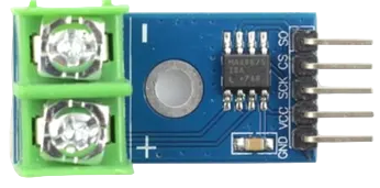
Pin Configuration and Descriptions

The MAX6675 module typically has 6 pins. Below is the pin configuration:

Pin Name Pin Number Description
VCC 1 Power supply input (3.0V to 5.5V)
GND 2 Ground
SCK 3 Serial Clock Input (SPI clock)
CS 4 Chip Select (active low)
SO 5 Serial Data Output (SPI data)
T- 6 Negative terminal for K-type thermocouple
T+ 7 Positive terminal for K-type thermocouple

Usage Instructions

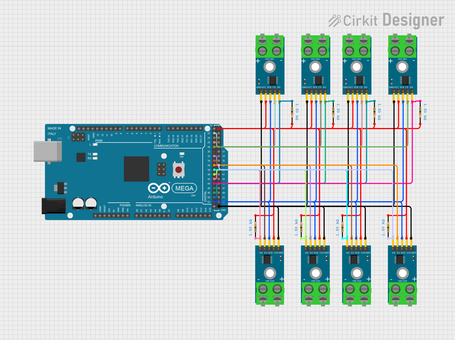
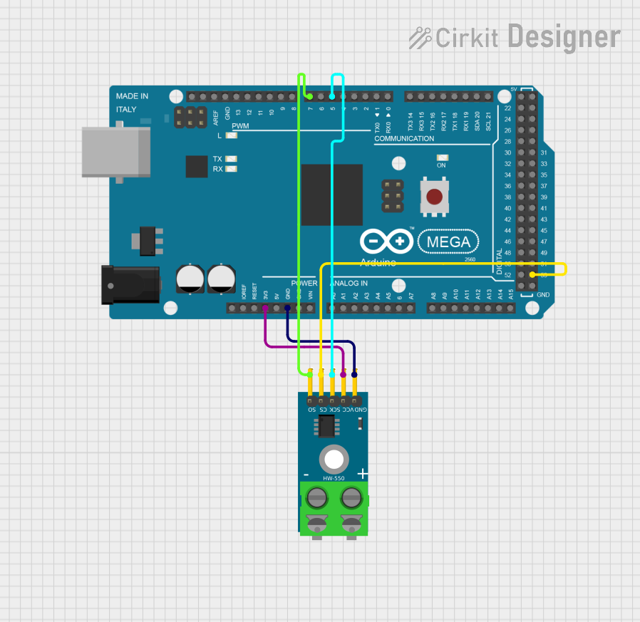
How to Use the MAX6675 in a Circuit

  1. Connect the Thermocouple: Attach the K-type thermocouple to the T+ and T- pins of the MAX6675 module.
  2. Power the Module: Connect the VCC pin to a 3.3V or 5V power source and the GND pin to ground.
  3. SPI Connections: Connect the SCK, CS, and SO pins to the corresponding SPI pins on your microcontroller. For example, when using an Arduino Nano:
    • SCK → D13 (SPI Clock)
    • CS → D10 (Chip Select)
    • SO → D12 (SPI Data Input)
  4. Load the Library: Use the Adafruit_MAX6675 library or a similar library to simplify communication with the module.
  5. Read Temperature: Use the library functions to read the temperature data and convert it to Celsius.

Important Considerations and Best Practices

  • Ensure the thermocouple is securely connected to the T+ and T- pins to avoid inaccurate readings.
  • Avoid exposing the thermocouple to temperatures beyond its rated range, as this may damage the sensor.
  • Use proper grounding to minimize noise and interference in the SPI communication.
  • If using a 5V microcontroller, ensure the MAX6675 module is compatible with 5V logic levels.

Example Code for Arduino Nano

Below is an example of how to interface the MAX6675 with an Arduino Nano to read temperature data:

#include <SPI.h>
#include "Adafruit_MAX6675.h"

// Define MAX6675 pins
const int SCK_PIN = 13;  // SPI Clock
const int CS_PIN = 10;   // Chip Select
const int SO_PIN = 12;   // SPI Data Input

// Initialize MAX6675 object
Adafruit_MAX6675 thermocouple(SCK_PIN, CS_PIN, SO_PIN);

void setup() {
  Serial.begin(9600);  // Start serial communication
  Serial.println("MAX6675 Temperature Sensor Test");
  delay(500);  // Allow time for initialization
}

void loop() {
  // Read temperature in Celsius
  double temperature = thermocouple.readCelsius();

  // Check if the reading is valid
  if (isnan(temperature)) {
    Serial.println("Error: Failed to read temperature!");
  } else {
    Serial.print("Temperature: ");
    Serial.print(temperature);
    Serial.println(" °C");
  }

  delay(1000);  // Wait 1 second before the next reading
}

Troubleshooting and FAQs

Common Issues and Solutions

  1. No Temperature Reading or NAN Output

    • Cause: Loose or incorrect connection of the thermocouple.
    • Solution: Ensure the thermocouple is securely connected to the T+ and T- pins.
  2. Inaccurate Temperature Readings

    • Cause: Electrical noise or interference in the SPI communication.
    • Solution: Use shorter wires for SPI connections and ensure proper grounding.
  3. Module Not Responding

    • Cause: Incorrect SPI pin configuration or power supply issues.
    • Solution: Double-check the wiring and ensure the module is powered with the correct voltage.
  4. Temperature Stuck at a Fixed Value

    • Cause: Faulty thermocouple or damaged MAX6675 module.
    • Solution: Test with a different thermocouple or replace the module.

FAQs

Q: Can the MAX6675 work with other thermocouple types?
A: No, the MAX6675 is specifically designed for K-type thermocouples. For other types, consider using a different module like the MAX31855.

Q: What is the maximum cable length for the thermocouple?
A: The maximum length depends on the thermocouple wire gauge and the environment. For best results, use shielded cables and keep the length under 10 meters.

Q: Can I use the MAX6675 with a 3.3V microcontroller?
A: Yes, the MAX6675 is compatible with both 3.3V and 5V logic levels.

Q: How do I calibrate the MAX6675?
A: The MAX6675 does not require calibration, but you can verify its accuracy by comparing its readings with a known reference thermometer.