How to Use Buck-Boost Converter: Examples, Pinouts, and Specs
Introduction
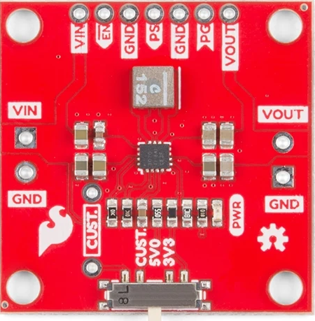
The Buck-Boost Converter (SparkFun COM-15208) is a versatile DC-DC converter capable of stepping up (boosting) or stepping down (bucking) an input voltage to achieve a stable output voltage. This functionality makes it ideal for applications where the input voltage can vary but a consistent output voltage is required. It is widely used in battery-powered devices, renewable energy systems, and embedded electronics.
Explore Projects Built with Buck-Boost Converter


Explore Projects Built with Buck-Boost Converter
Common Applications and Use Cases
- Powering microcontrollers and sensors from batteries with fluctuating voltage levels.
- Regulating voltage in portable devices such as smartphones, tablets, and wearables.
- Renewable energy systems, such as solar panels, where input voltage varies with environmental conditions.
- Automotive electronics to stabilize voltage from a car battery.
- Any circuit requiring a stable voltage output from a variable input source.
Technical Specifications
The following table outlines the key technical details of the SparkFun COM-15208 Buck-Boost Converter:
| Parameter | Value |
|---|---|
| Input Voltage Range | 2.7V to 11.8V |
| Output Voltage Range | 2.5V to 9.0V (adjustable via potentiometer) |
| Maximum Output Current | 2A (depending on input/output conditions) |
| Efficiency | Up to 90% (varies with load and voltage) |
| Switching Frequency | 1.2 MHz |
| Dimensions | 22.9mm x 20.3mm |
| Operating Temperature | -40°C to +85°C |
Pin Configuration and Descriptions
The SparkFun COM-15208 Buck-Boost Converter has the following pinout:
| Pin Name | Description |
|---|---|
| VIN | Input voltage pin (connect to the power source). |
| GND | Ground pin (common ground for input and output). |
| VOUT | Output voltage pin (connect to the load). |
| EN | Enable pin (active high, enables the converter). |
| FB | Feedback pin (used for voltage regulation). |
Usage Instructions
How to Use the Buck-Boost Converter in a Circuit
Connect the Input Voltage (VIN):
- Attach the positive terminal of your power source to the VIN pin.
- Connect the negative terminal of your power source to the GND pin.
Set the Desired Output Voltage:
- Use the onboard potentiometer to adjust the output voltage.
- Measure the output voltage at the VOUT pin using a multimeter while adjusting the potentiometer.
Connect the Load:
- Attach the positive terminal of your load to the VOUT pin.
- Connect the negative terminal of your load to the GND pin.
Enable the Converter:
- Ensure the EN pin is pulled high (connect to VIN or a logic high signal) to enable the converter.
- If the EN pin is left floating or pulled low, the converter will be disabled.
Important Considerations and Best Practices
- Input Voltage Range: Ensure the input voltage remains within the specified range (2.7V to 11.8V) to avoid damaging the converter.
- Output Current Limit: Do not exceed the maximum output current of 2A to prevent overheating or failure.
- Heat Dissipation: For high current loads, consider adding a heatsink or improving airflow around the converter to manage heat.
- Noise Filtering: Add input and output capacitors (e.g., 10µF to 100µF) close to the VIN and VOUT pins to reduce noise and improve stability.
- Feedback Pin (FB): Avoid accidental connections to the FB pin, as it is used internally for voltage regulation.
Example: Using the Buck-Boost Converter with an Arduino UNO
The Buck-Boost Converter can be used to power an Arduino UNO from a battery. Below is an example circuit and code:
Circuit Connections
- Connect the battery's positive terminal to the VIN pin of the converter.
- Connect the battery's negative terminal to the GND pin of the converter.
- Adjust the output voltage to 5V using the potentiometer.
- Connect the VOUT pin of the converter to the 5V pin of the Arduino UNO.
- Connect the GND pin of the converter to the GND pin of the Arduino UNO.
Arduino Code Example
// Example code to read a sensor powered by the Buck-Boost Converter
// Ensure the converter is set to output 5V for the Arduino UNO

const int sensorPin = A0; // Analog pin connected to the sensor
int sensorValue = 0;      // Variable to store the sensor reading

void setup() {
  Serial.begin(9600); // Initialize serial communication at 9600 baud
  pinMode(sensorPin, INPUT); // Set the sensor pin as input
}

void loop() {
  sensorValue = analogRead(sensorPin); // Read the sensor value
  Serial.print("Sensor Value: ");
  Serial.println(sensorValue); // Print the sensor value to the Serial Monitor
  delay(1000); // Wait for 1 second before the next reading
}
Troubleshooting and FAQs
Common Issues and Solutions
No Output Voltage:
- Cause: The EN pin is not connected or is pulled low.
Solution: Ensure the EN pin is connected to VIN or a logic high signal. - Cause: Input voltage is outside the specified range.
Solution: Verify the input voltage is between 2.7V and 11.8V.
- Cause: The EN pin is not connected or is pulled low.
Output Voltage is Incorrect:
- Cause: The potentiometer is not adjusted correctly.
Solution: Use a multimeter to measure and adjust the output voltage. - Cause: Excessive load current.
Solution: Ensure the load current does not exceed 2A.
- Cause: The potentiometer is not adjusted correctly.
Overheating:
- Cause: High current draw or poor ventilation.
Solution: Reduce the load current or improve heat dissipation with a heatsink.
- Cause: High current draw or poor ventilation.
Noise or Instability:
- Cause: Insufficient input/output capacitors.
Solution: Add capacitors (10µF to 100µF) close to the VIN and VOUT pins.
- Cause: Insufficient input/output capacitors.
FAQs
Q: Can the Buck-Boost Converter handle reverse polarity on the input?
A: No, the converter does not have reverse polarity protection. Always ensure correct polarity when connecting the input voltage.
Q: Can I use the Buck-Boost Converter to power a Raspberry Pi?
A: Yes, but ensure the output voltage is set to 5V and the load current does not exceed 2A.
Q: How do I know if the converter is working correctly?
A: Measure the output voltage with a multimeter and verify it matches the desired value. Additionally, check for stable operation under load.
Q: Can I use the Buck-Boost Converter with a solar panel?
A: Yes, as long as the solar panel's output voltage is within the input range (2.7V to 11.8V).