Cirkit Designer Logo
Cirkit Designer
Your all-in-one circuit design IDE
Home / 
Component Documentation

How to Use PowerBoost 1000 Basic Pad Terminal: Examples, Pinouts, and Specs

Image of PowerBoost 1000 Basic Pad Terminal
Cirkit Designer LogoDesign with PowerBoost 1000 Basic Pad Terminal in Cirkit Designer

Introduction

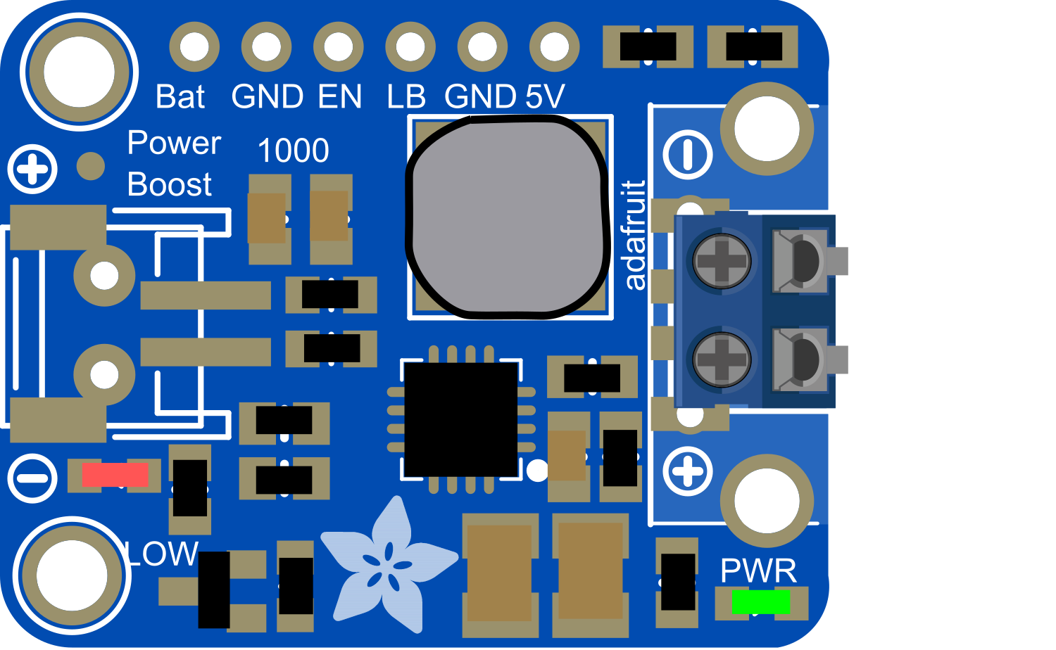
The PowerBoost 1000 Basic is a versatile and efficient power supply module designed to provide a stable 5V output from a single lithium polymer (LiPo) battery. It is an ideal solution for portable electronics, wearables, and projects that require a rechargeable power source. With its built-in charging circuit, users can easily recharge the battery without the need for a separate charger. The pad terminals on the PowerBoost 1000 Basic facilitate easy soldering, making it a convenient choice for DIY enthusiasts and professionals alike.

Explore Projects Built with PowerBoost 1000 Basic Pad Terminal

Use Cirkit Designer to design, explore, and prototype these projects online. Some projects support real-time simulation. Click "Open Project" to start designing instantly!
Arduino Mega 2560 Based Security System with Fingerprint Authentication and SMS Alerts
Image of Door security system: A project utilizing PowerBoost 1000 Basic Pad Terminal in a practical application
This circuit features an Arduino Mega 2560 microcontroller interfaced with a SIM800L GSM module, two fingerprint scanners, an I2C LCD display, an IR sensor, and a piezo buzzer. Power management is handled by a PowerBoost 1000 Basic Pad USB, a TP4056 charging module, and a Li-ion 18650 battery, with an option to use a Mini AC-DC 110V-230V to 5V 700mA module for direct power supply. The primary functionality appears to be a security system with GSM communication capabilities, biometric access control, and visual/audible feedback.
Cirkit Designer LogoOpen Project in Cirkit Designer
Battery-Powered Piezo Sensor Array with PowerBoost and Bridge Rectifier
Image of Copy of PIEZOELECTRIC : A project utilizing PowerBoost 1000 Basic Pad Terminal in a practical application
This circuit uses multiple piezo sensors connected to bridge rectifiers to convert AC signals from the sensors into DC. The rectified DC is then used to charge a 18650 Li-ion battery, which powers a PowerBoost 1000 Basic module to provide a stable 5V output.
Cirkit Designer LogoOpen Project in Cirkit Designer
Battery-Powered Raspberry Pi Zero with OLED Display and EmStat Pico for Portable Data Acquisition
Image of RPI Zero Prototype: A project utilizing PowerBoost 1000 Basic Pad Terminal in a practical application
This circuit is a portable system powered by a 3.7V LiPo battery, which is boosted to 5V using an Adafruit PowerBoost 1000C to power a Raspberry Pi Zero and an EmStat Pico. The Raspberry Pi Zero interfaces with an OLED display via I2C and a tactile switch for user input, while the EmStat Pico communicates with the Raspberry Pi over UART for data acquisition or control purposes.
Cirkit Designer LogoOpen Project in Cirkit Designer
Modular Power Distribution System with Multiple SMPS Units and 120V Outlet
Image of Cellion-Tesla: A project utilizing PowerBoost 1000 Basic Pad Terminal in a practical application
This circuit is designed to convert 240V AC power to both 12V and 24V DC outputs using multiple SMPS units. Terminal blocks are used to organize and distribute the power, while a 120V outlet provides additional AC power access. The circuit is likely used for powering various electronic devices that require different voltage levels.
Cirkit Designer LogoOpen Project in Cirkit Designer

Explore Projects Built with PowerBoost 1000 Basic Pad Terminal

Use Cirkit Designer to design, explore, and prototype these projects online. Some projects support real-time simulation. Click "Open Project" to start designing instantly!
Image of Door security system: A project utilizing PowerBoost 1000 Basic Pad Terminal in a practical application
Arduino Mega 2560 Based Security System with Fingerprint Authentication and SMS Alerts
This circuit features an Arduino Mega 2560 microcontroller interfaced with a SIM800L GSM module, two fingerprint scanners, an I2C LCD display, an IR sensor, and a piezo buzzer. Power management is handled by a PowerBoost 1000 Basic Pad USB, a TP4056 charging module, and a Li-ion 18650 battery, with an option to use a Mini AC-DC 110V-230V to 5V 700mA module for direct power supply. The primary functionality appears to be a security system with GSM communication capabilities, biometric access control, and visual/audible feedback.
Cirkit Designer LogoOpen Project in Cirkit Designer
Image of Copy of PIEZOELECTRIC : A project utilizing PowerBoost 1000 Basic Pad Terminal in a practical application
Battery-Powered Piezo Sensor Array with PowerBoost and Bridge Rectifier
This circuit uses multiple piezo sensors connected to bridge rectifiers to convert AC signals from the sensors into DC. The rectified DC is then used to charge a 18650 Li-ion battery, which powers a PowerBoost 1000 Basic module to provide a stable 5V output.
Cirkit Designer LogoOpen Project in Cirkit Designer
Image of RPI Zero Prototype: A project utilizing PowerBoost 1000 Basic Pad Terminal in a practical application
Battery-Powered Raspberry Pi Zero with OLED Display and EmStat Pico for Portable Data Acquisition
This circuit is a portable system powered by a 3.7V LiPo battery, which is boosted to 5V using an Adafruit PowerBoost 1000C to power a Raspberry Pi Zero and an EmStat Pico. The Raspberry Pi Zero interfaces with an OLED display via I2C and a tactile switch for user input, while the EmStat Pico communicates with the Raspberry Pi over UART for data acquisition or control purposes.
Cirkit Designer LogoOpen Project in Cirkit Designer
Image of Cellion-Tesla: A project utilizing PowerBoost 1000 Basic Pad Terminal in a practical application
Modular Power Distribution System with Multiple SMPS Units and 120V Outlet
This circuit is designed to convert 240V AC power to both 12V and 24V DC outputs using multiple SMPS units. Terminal blocks are used to organize and distribute the power, while a 120V outlet provides additional AC power access. The circuit is likely used for powering various electronic devices that require different voltage levels.
Cirkit Designer LogoOpen Project in Cirkit Designer

Common Applications and Use Cases

  • Portable USB chargers
  • Wearable electronics
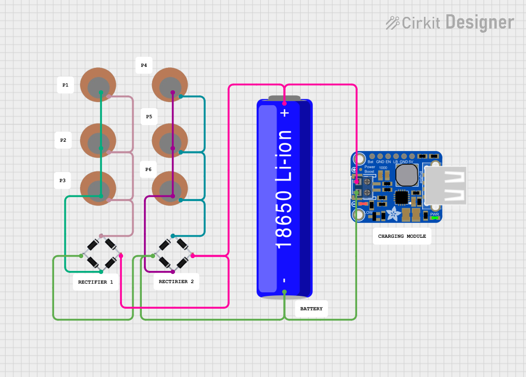
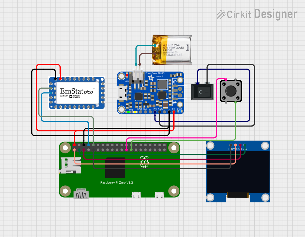
  • Battery-powered Raspberry Pi projects
  • Mobile robotics
  • DIY electronics projects requiring a 5V power supply

Technical Specifications

Key Technical Details

  • Input Voltage: 3.7V nominal (LiPo battery)
  • Output Voltage: 5V regulated output
  • Maximum Output Current: 1A
  • Charging Current: Up to 1000mA
  • Efficiency: 90% typical at full load
  • Low Battery Indicator: Yes

Pin Configuration and Descriptions

Pin Name Description
BAT Battery input terminal for LiPo battery connection
GND Ground connection
5V Regulated 5V output
EN Enable pin for turning the module on/off
USB USB power output, can be used to charge devices
LBO Low Battery Output, goes low when the battery is low

Usage Instructions

How to Use the Component in a Circuit

  1. Connecting the Battery:

    • Solder the positive terminal of the LiPo battery to the BAT pad.
    • Connect the negative terminal of the battery to the GND pad.
  2. Drawing Power:

    • Connect your device's power input to the 5V and GND pads for a regulated 5V supply.
  3. Charging the Battery:

    • Connect a 5V source to the USB pad to charge the connected LiPo battery.
  4. Enabling/Disabling Power Output:

    • Connect the EN pad to GND to disable the 5V output.
    • Leave the EN pad floating to enable the 5V output.
  5. Monitoring Battery Status:

    • Connect an LED or a digital input of a microcontroller to the LBO pad to monitor the battery status.

Important Considerations and Best Practices

  • Ensure the LiPo battery voltage does not exceed the module's input voltage range.
  • Do not short-circuit the output terminals.
  • Avoid placing the module in a high-temperature environment to prevent overheating.
  • When soldering, be careful not to overheat the pad terminals.
  • Always disconnect the battery when not in use to prevent over-discharge.

Troubleshooting and FAQs

Common Issues

  • No Output Voltage:

    • Check if the battery is charged and properly connected.
    • Ensure the EN pad is not inadvertently connected to GND.
  • Battery Not Charging:

    • Verify that the 5V source is connected to the USB pad and is supplying power.
    • Check for any loose connections or cold solder joints.
  • Low Battery Indicator Always On:

    • Ensure the battery is fully charged.
    • If the issue persists, the battery may be damaged and need replacement.

Solutions and Tips for Troubleshooting

  • Double-check all connections and solder joints for continuity.
  • Use a multimeter to verify the input and output voltages.
  • If the module becomes hot, disconnect it immediately and check for any issues with the circuit or battery.

FAQs

Q: Can I use the PowerBoost 1000 Basic to power a Raspberry Pi? A: Yes, the PowerBoost 1000 Basic can power a Raspberry Pi as it provides a stable 5V output.

Q: How do I know when the battery is fully charged? A: The module does not have a dedicated charge indicator. You will need to monitor the battery voltage or use an external charging indicator circuit.

Q: Is it possible to increase the charging current? A: The charging current is set to a maximum of 1000mA and should not be increased to ensure the safety and longevity of the battery.

Q: Can I use the PowerBoost 1000 Basic with batteries other than LiPo? A: The PowerBoost 1000 Basic is specifically designed for LiPo batteries. Using other types of batteries is not recommended and may damage the module.

For any further assistance or technical support, please contact the manufacturer or visit the official product forum.