Cirkit Designer Logo
Cirkit Designer
Your all-in-one circuit design IDE
Home / 
Component Documentation

How to Use Adafruit MAX9744 20W Amplifier: Examples, Pinouts, and Specs

Image of Adafruit MAX9744 20W Amplifier
Cirkit Designer LogoDesign with Adafruit MAX9744 20W Amplifier in Cirkit Designer

Introduction

The Adafruit MAX9744 20W Amplifier is a high-quality class D audio amplifier capable of delivering up to 20 watts of power per channel into a pair of speakers. With its high efficiency and low distortion, it is an excellent choice for a wide range of audio applications, from DIY home projects to interactive installations.

Explore Projects Built with Adafruit MAX9744 20W Amplifier

Use Cirkit Designer to design, explore, and prototype these projects online. Some projects support real-time simulation. Click "Open Project" to start designing instantly!
Dual-Microcontroller Audio Processing System with Visual Indicators and Battery Management
Image of proto thesis 2: A project utilizing Adafruit MAX9744 20W Amplifier in a practical application
This is a portable audio-visual device featuring two Wemos microcontrollers for processing, Adafruit MAX4466 microphone amplifiers for audio input, and an LCD TFT screen for display. It includes power management with TP4056 modules and LiPo batteries, and user-controlled toggle and rocker switches.
Cirkit Designer LogoOpen Project in Cirkit Designer
ESP32-Based Wi-Fi Controlled Audio Processing System
Image of resona : A project utilizing Adafruit MAX9744 20W Amplifier in a practical application
This circuit features an ESP32 microcontroller interfaced with an Adafruit MAX9814 Electret Microphone Amplifier for audio input and a Max98357 amplifier connected to a speaker for audio output. The ESP32 processes the audio signals from the microphone and sends the processed data to the speaker through the Max98357 amplifier.
Cirkit Designer LogoOpen Project in Cirkit Designer
Voice-Activated ESP32 & Wemos Controllers with TFT Display and Battery Management
Image of prototype schematic: A project utilizing Adafruit MAX9744 20W Amplifier in a practical application
This circuit features multiple microcontroller units (MCUs) including a Wemos S2 Mini, Wemos D1 Mini, and an ESP32 Devkit V1, each interfaced with an Adafruit MAX4466 Electret Microphone Amplifier for audio input and an LCD TFT screen for display output. The circuit is powered by Polymer Lithium Ion Batteries connected through TP4056 charging modules, with power management facilitated by push and rocker switches. The primary function of this circuit appears to be audio capture and processing with visual feedback.
Cirkit Designer LogoOpen Project in Cirkit Designer
PAM8403 Amplified Piezo Speaker Array with ATTiny Control
Image of mamamo: A project utilizing Adafruit MAX9744 20W Amplifier in a practical application
This circuit is an audio amplification system with multiple piezo speakers driven by a PAM8403 amplifier IC. It features an ATtiny microcontroller for potential audio control, powered by a 5V battery with capacitors for stabilization and a trimmer potentiometer for input level adjustment.
Cirkit Designer LogoOpen Project in Cirkit Designer

Explore Projects Built with Adafruit MAX9744 20W Amplifier

Use Cirkit Designer to design, explore, and prototype these projects online. Some projects support real-time simulation. Click "Open Project" to start designing instantly!
Image of proto thesis 2: A project utilizing Adafruit MAX9744 20W Amplifier in a practical application
Dual-Microcontroller Audio Processing System with Visual Indicators and Battery Management
This is a portable audio-visual device featuring two Wemos microcontrollers for processing, Adafruit MAX4466 microphone amplifiers for audio input, and an LCD TFT screen for display. It includes power management with TP4056 modules and LiPo batteries, and user-controlled toggle and rocker switches.
Cirkit Designer LogoOpen Project in Cirkit Designer
Image of resona : A project utilizing Adafruit MAX9744 20W Amplifier in a practical application
ESP32-Based Wi-Fi Controlled Audio Processing System
This circuit features an ESP32 microcontroller interfaced with an Adafruit MAX9814 Electret Microphone Amplifier for audio input and a Max98357 amplifier connected to a speaker for audio output. The ESP32 processes the audio signals from the microphone and sends the processed data to the speaker through the Max98357 amplifier.
Cirkit Designer LogoOpen Project in Cirkit Designer
Image of prototype schematic: A project utilizing Adafruit MAX9744 20W Amplifier in a practical application
Voice-Activated ESP32 & Wemos Controllers with TFT Display and Battery Management
This circuit features multiple microcontroller units (MCUs) including a Wemos S2 Mini, Wemos D1 Mini, and an ESP32 Devkit V1, each interfaced with an Adafruit MAX4466 Electret Microphone Amplifier for audio input and an LCD TFT screen for display output. The circuit is powered by Polymer Lithium Ion Batteries connected through TP4056 charging modules, with power management facilitated by push and rocker switches. The primary function of this circuit appears to be audio capture and processing with visual feedback.
Cirkit Designer LogoOpen Project in Cirkit Designer
Image of mamamo: A project utilizing Adafruit MAX9744 20W Amplifier in a practical application
PAM8403 Amplified Piezo Speaker Array with ATTiny Control
This circuit is an audio amplification system with multiple piezo speakers driven by a PAM8403 amplifier IC. It features an ATtiny microcontroller for potential audio control, powered by a 5V battery with capacitors for stabilization and a trimmer potentiometer for input level adjustment.
Cirkit Designer LogoOpen Project in Cirkit Designer

Common Applications and Use Cases

  • DIY audio projects
  • Portable speakers
  • Interactive sound installations
  • Home theater systems
  • Desktop audio amplification

Technical Specifications

Key Technical Details

  • Supply Voltage: 4.5V to 14V DC
  • Output Power: Up to 20W per channel into 4Ω speakers
  • Efficiency: Up to 93%
  • Total Harmonic Distortion (THD): <0.1%
  • Signal-to-Noise Ratio (SNR): >90dB
  • Gain: 20dB to 50dB in 32 steps
  • I2C Address: 0x4B (default)

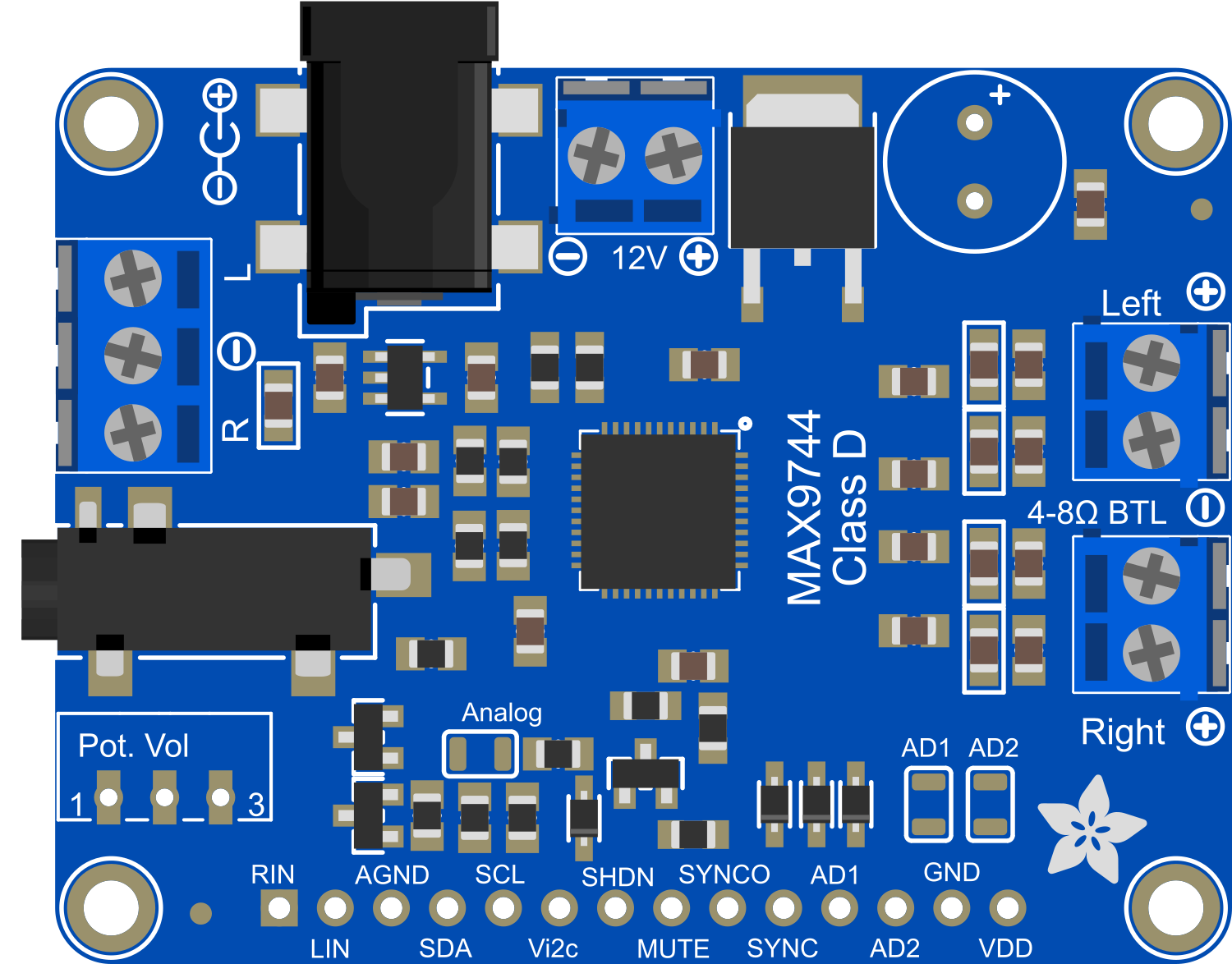
Pin Configuration and Descriptions

Pin Number Pin Name Description
1 GND Ground connection
2 VDD Supply voltage (4.5V to 14V DC)
3 IN+ Positive audio input
4 IN- Negative audio input
5 GAIN Gain control pin
6 SD Shutdown control pin
7 OUT+ Positive speaker output
8 OUT- Negative speaker output

Usage Instructions

How to Use the Component in a Circuit

  1. Power Supply: Connect a DC power supply between the VDD and GND pins. Ensure that the voltage is within the specified range (4.5V to 14V DC).
  2. Audio Input: Connect the audio source to the IN+ and IN- pins. This can be a stereo jack or directly from an audio device.
  3. Speaker Connection: Connect the speakers to the OUT+ and OUT- pins. Ensure that the speakers are rated for the output power and have an impedance of 4Ω.
  4. Gain Control: The gain can be adjusted via the GAIN pin or through I2C communication.
  5. Shutdown Control: The SD pin can be used to put the amplifier into a low-power shutdown mode.

Important Considerations and Best Practices

  • Always ensure that the power supply voltage does not exceed the maximum rating.
  • Use proper decoupling capacitors close to the power supply pins to minimize noise.
  • Avoid running audio input cables near sources of high electrical noise.
  • Ensure that the speakers are correctly rated for the amplifier's output power to prevent damage.
  • Use shielded cables for audio inputs to reduce interference.

Troubleshooting and FAQs

Common Issues

  • No Sound Output: Check power supply connections, ensure that the SD pin is not pulling the device into shutdown mode, and verify that the audio input is connected correctly.
  • Distorted Sound: Ensure that the speakers are not overloaded, check for proper gain settings, and verify that the power supply is stable and within the specified range.
  • Overheating: Make sure that the amplifier is not driving a load lower than 4Ω and that it has adequate ventilation.

Solutions and Tips for Troubleshooting

  • Power Supply Issues: Use a multimeter to verify the voltage at the VDD pin.
  • Audio Quality: If the audio quality is poor, check for loose connections and ensure that the input signal is not too high, causing clipping.
  • I2C Communication: If using I2C to control the amplifier, ensure that the connections are correct and that the correct I2C address is being used.

FAQs

Q: Can I use 8Ω speakers with this amplifier? A: Yes, but the maximum output power will be lower than with 4Ω speakers.

Q: How do I adjust the volume using I2C? A: You can send volume control commands to the I2C address of the amplifier to adjust the gain.

Q: What should I do if the amplifier gets too hot? A: Ensure proper ventilation and check that the speaker impedance is not too low.

Example Arduino Code

Below is an example of how to control the Adafruit MAX9744 20W Amplifier using an Arduino UNO:

#include <Wire.h>

// Define the I2C address for the amplifier
#define AMP_I2C_ADDRESS 0x4B

void setup() {
  Wire.begin(); // Start the I2C bus
  Serial.begin(9600); // Start serial communication for debugging
  setVolume(20); // Set initial volume to 20%
}

void loop() {
  // Volume control code can be added here
}

// Function to set the volume of the amplifier
void setVolume(uint8_t volume) {
  if (volume > 63) {
    volume = 63; // Maximum volume level is 63
  }
  Wire.beginTransmission(AMP_I2C_ADDRESS);
  Wire.write(volume); // Send volume level over I2C
  Wire.endTransmission();
  Serial.print("Volume set to: ");
  Serial.println(volume);
}

Remember to include comments in your code to explain each step, and ensure that the comments do not exceed 80 characters per line. This will make your code more readable and maintainable.