How to Use DFRobot Gravity Analog high Electrical Conductivity Sensor Meter K=10: Examples, Pinouts, and Specs
Introduction
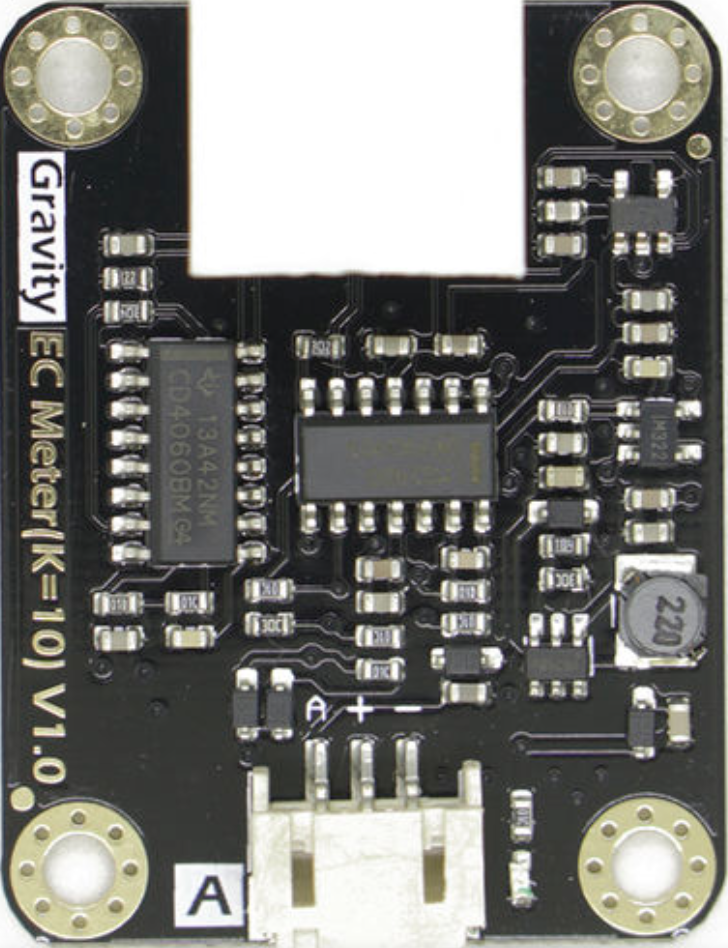
The DFRobot Gravity Analog High Electrical Conductivity Sensor Meter K=10 is a specialized sensor designed to measure the electrical conductivity (EC) of liquids. It provides an analog output proportional to the conductivity level, making it ideal for applications requiring precise water quality monitoring. This sensor is particularly suited for high-conductivity solutions, such as seawater or industrial liquids, due to its K=10 probe constant.
Explore Projects Built with DFRobot Gravity Analog high Electrical Conductivity Sensor Meter K=10
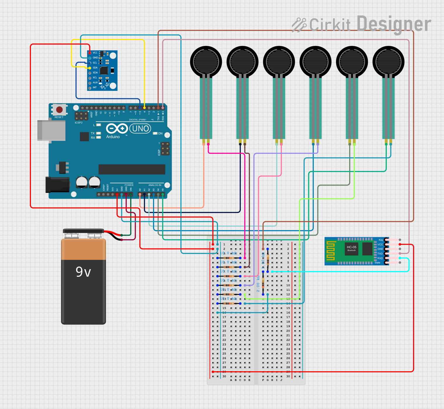
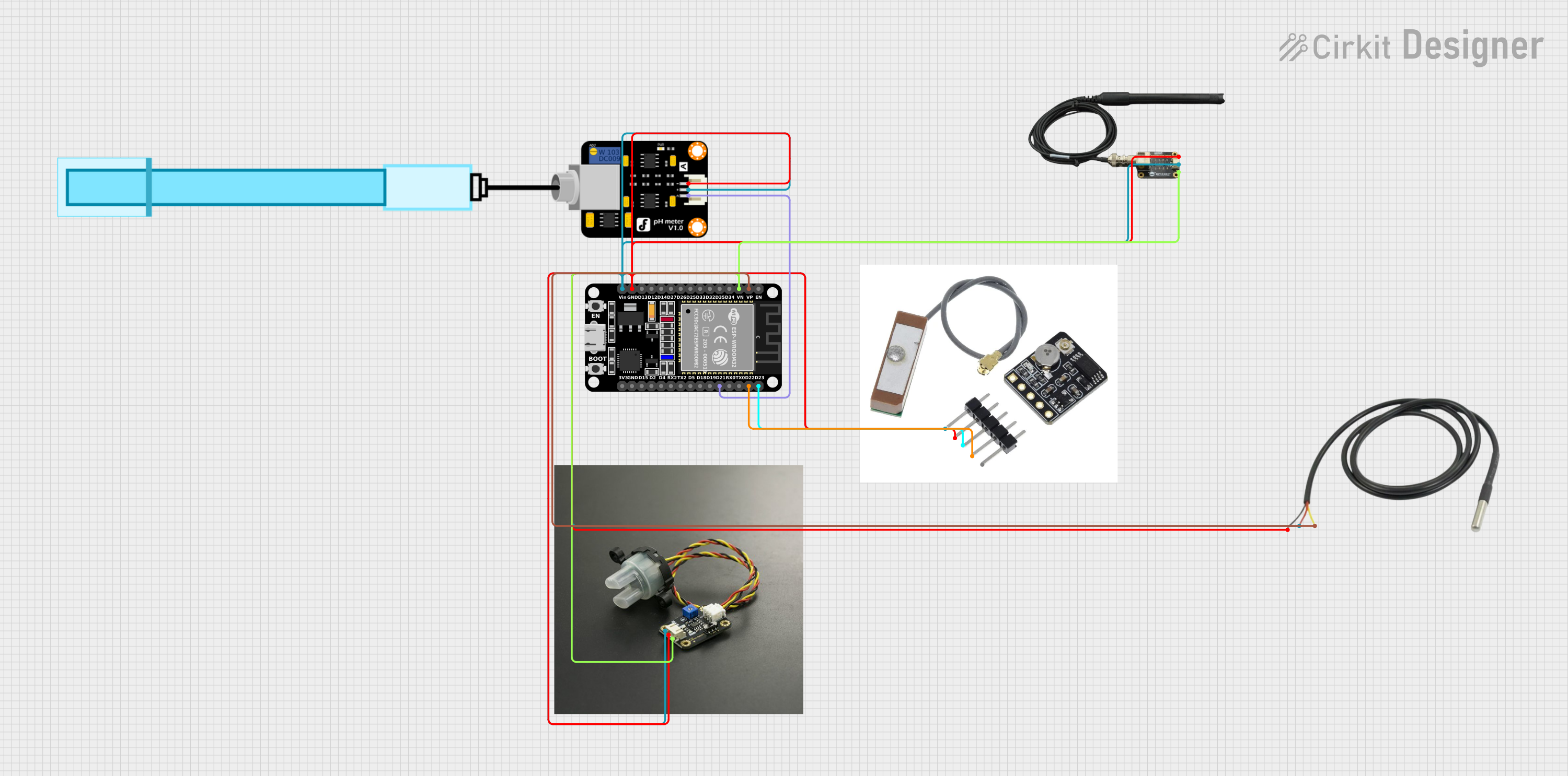
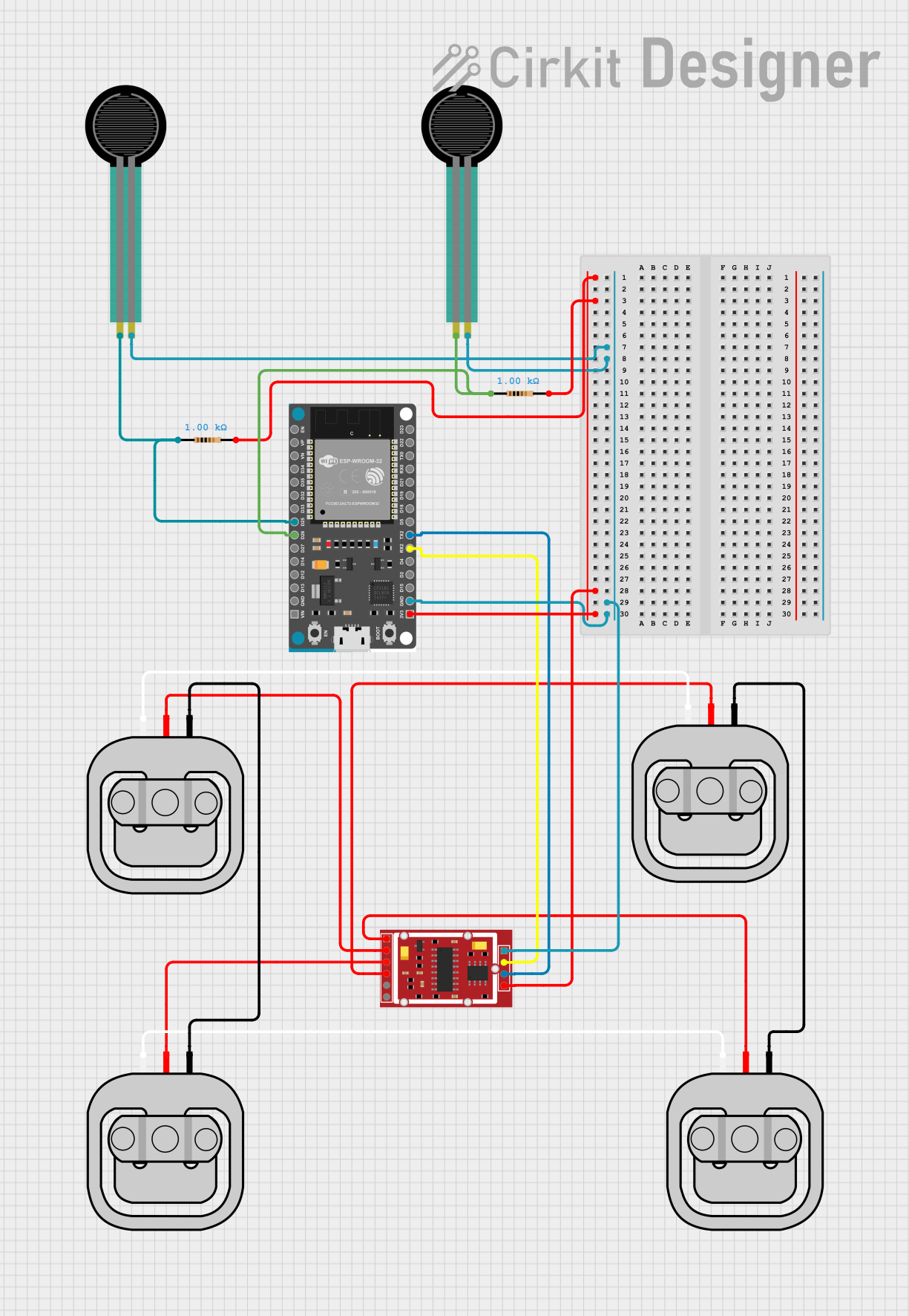

Explore Projects Built with DFRobot Gravity Analog high Electrical Conductivity Sensor Meter K=10
Common Applications and Use Cases
- Water quality monitoring in aquariums, hydroponics, and aquaculture
- Environmental testing of rivers, lakes, and oceans
- Industrial process control for monitoring liquid conductivity
- Research and development in chemical and biological fields
Technical Specifications
The following table outlines the key technical details of the DFRobot Gravity Analog High Electrical Conductivity Sensor Meter K=10:
| Parameter | Value |
|---|---|
| Operating Voltage | 3.3V - 5.5V |
| Output Signal | Analog (0-3.4V) |
| Measurement Range | 0 - 100 mS/cm |
| Probe Constant (K) | 10 |
| Temperature Compensation | Supported (10°C - 40°C) |
| Accuracy | ±2% Full Scale |
| Response Time | < 1 second |
| Interface | Gravity 3-pin interface |
| Dimensions | 42mm x 32mm (control board) |
| Probe Material | Platinum black |
| Cable Length | 1 meter |
Pin Configuration and Descriptions
The sensor features a 3-pin Gravity interface for easy connection. The pin configuration is as follows:
| Pin | Name | Description |
|---|---|---|
| 1 | VCC | Power supply input (3.3V - 5.5V) |
| 2 | GND | Ground connection |
| 3 | Signal | Analog output signal proportional to conductivity |
Usage Instructions
How to Use the Sensor in a Circuit
Connect the Sensor to a Microcontroller:
- Connect the
VCCpin to the 5V (or 3.3V) power supply of your microcontroller. - Connect the
GNDpin to the ground (GND) of your microcontroller. - Connect the
Signalpin to an analog input pin on your microcontroller (e.g., A0 on an Arduino UNO).
- Connect the
Calibrate the Sensor:
- Use a standard solution with a known conductivity value to calibrate the sensor.
- Adjust the calibration potentiometer on the control board to match the expected output.
Place the Probe in the Liquid:
- Submerge the probe in the liquid to be measured. Ensure the probe is fully immersed and free of air bubbles.
Read the Analog Output:
- Use the microcontroller to read the analog signal and convert it to a conductivity value using the provided formula or library.
Important Considerations and Best Practices
- Temperature Compensation: The sensor includes temperature compensation for accurate readings. Ensure the liquid temperature is within the supported range (10°C - 40°C).
- Probe Maintenance: Clean the probe regularly to prevent fouling, especially when used in dirty or high-salinity environments.
- Avoid Damage: Do not expose the probe to strong acids, bases, or organic solvents, as this may damage the platinum black coating.
- Calibration Frequency: Recalibrate the sensor periodically to maintain accuracy, especially if used in varying conditions.
Example Code for Arduino UNO
Below is an example of how to use the sensor with an Arduino UNO:
// DFRobot Gravity Analog High Electrical Conductivity Sensor Example
// Connect the sensor's Signal pin to A0 on the Arduino UNO

const int sensorPin = A0;  // Analog pin connected to the sensor's Signal pin
float voltage;             // Variable to store the sensor's output voltage
float conductivity;        // Variable to store the calculated conductivity

void setup() {
  Serial.begin(9600);  // Initialize serial communication
  pinMode(sensorPin, INPUT);  // Set the sensor pin as input
}

void loop() {
  // Read the analog value from the sensor
  int sensorValue = analogRead(sensorPin);

  // Convert the analog value to voltage (assuming 5V reference)
  voltage = sensorValue * (5.0 / 1023.0);

  // Convert the voltage to conductivity (mS/cm)
  // Formula: Conductivity = (Voltage / 3.4) * 100 (for K=10 probe)
  conductivity = (voltage / 3.4) * 100;

  // Print the conductivity value to the Serial Monitor
  Serial.print("Conductivity: ");
  Serial.print(conductivity);
  Serial.println(" mS/cm");

  delay(1000);  // Wait for 1 second before the next reading
}
Troubleshooting and FAQs
Common Issues and Solutions
No Output or Incorrect Readings:
- Cause: Loose or incorrect connections.
- Solution: Verify all connections are secure and match the pin configuration.
Unstable or Fluctuating Readings:
- Cause: Air bubbles on the probe or electrical noise.
- Solution: Ensure the probe is fully submerged and free of air bubbles. Use shielded cables or place the sensor away from noise sources.
Inaccurate Measurements:
- Cause: Calibration drift or dirty probe.
- Solution: Recalibrate the sensor using a standard solution. Clean the probe with distilled water and a soft brush.
Sensor Not Responding:
- Cause: Damaged probe or control board.
- Solution: Inspect the probe and control board for physical damage. Replace if necessary.
FAQs
Q: Can this sensor measure the conductivity of pure water?
A: No, pure water has very low conductivity, which is outside the sensor's measurement range. It is better suited for solutions with higher conductivity, such as seawater or industrial liquids.
Q: How often should I calibrate the sensor?
A: Calibration frequency depends on usage. For critical applications, calibrate before each use. For general use, calibrate monthly or as needed.
Q: Can I use this sensor with a 3.3V microcontroller?
A: Yes, the sensor supports an operating voltage range of 3.3V to 5.5V, making it compatible with 3.3V systems.
Q: What is the lifespan of the probe?
A: The probe's lifespan depends on usage and maintenance. With proper care, it can last several years. Regular cleaning and avoiding exposure to harsh chemicals will extend its life.