How to Use Adafruit MAX98357A: Examples, Pinouts, and Specs
Introduction
The Adafruit MAX98357A is a compact, highly efficient Class D amplifier that is designed to deliver high-quality audio amplification. This breakout board is specifically tailored for use with digital I2S audio signals, making it an ideal choice for projects involving the Raspberry Pi or other microcontrollers and development boards with I2S output capabilities. Its ease of use and low power consumption make it suitable for a wide range of applications, including DIY audio projects, portable speakers, and Internet of Things (IoT) audio applications.
Explore Projects Built with Adafruit MAX98357A

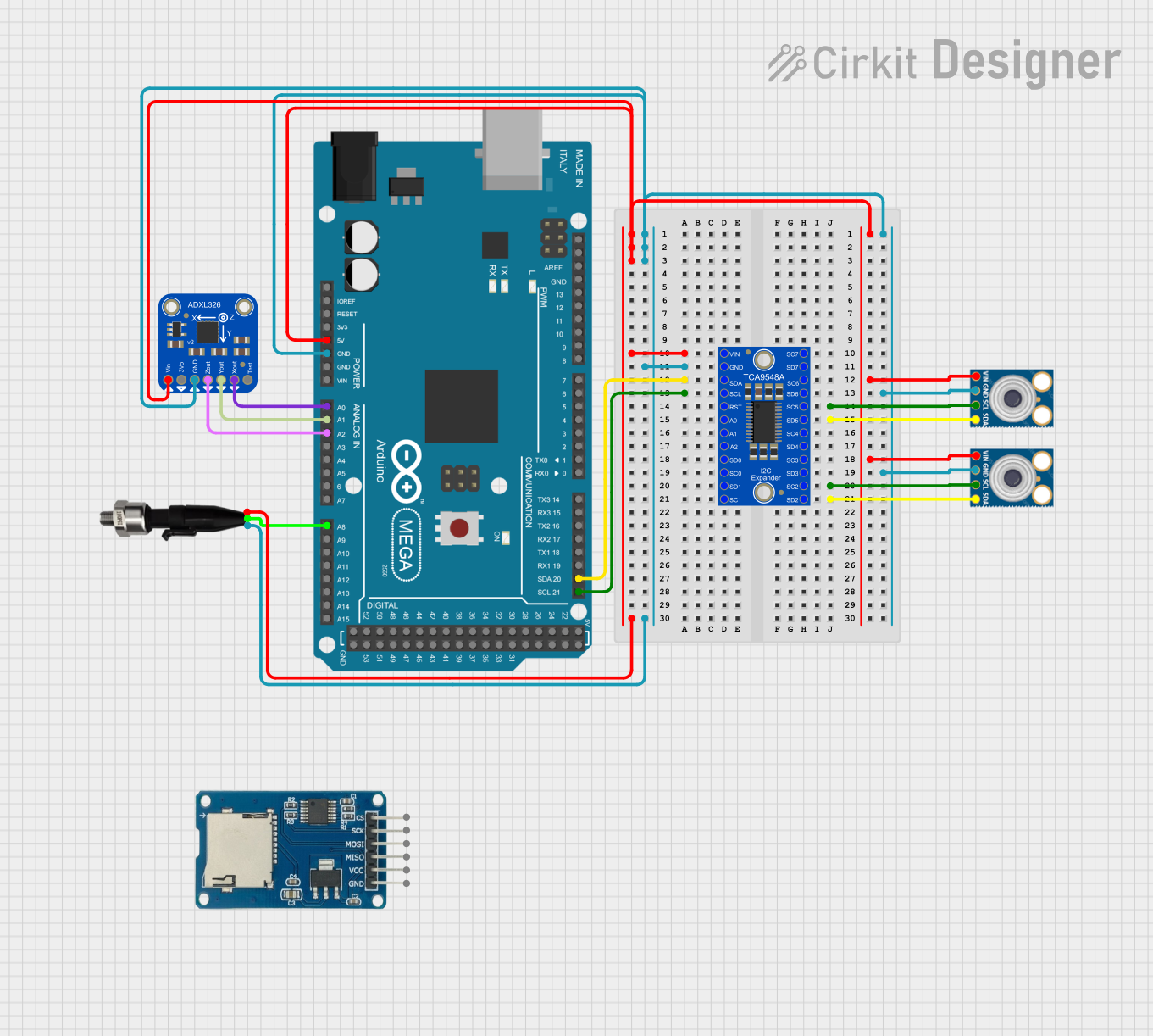
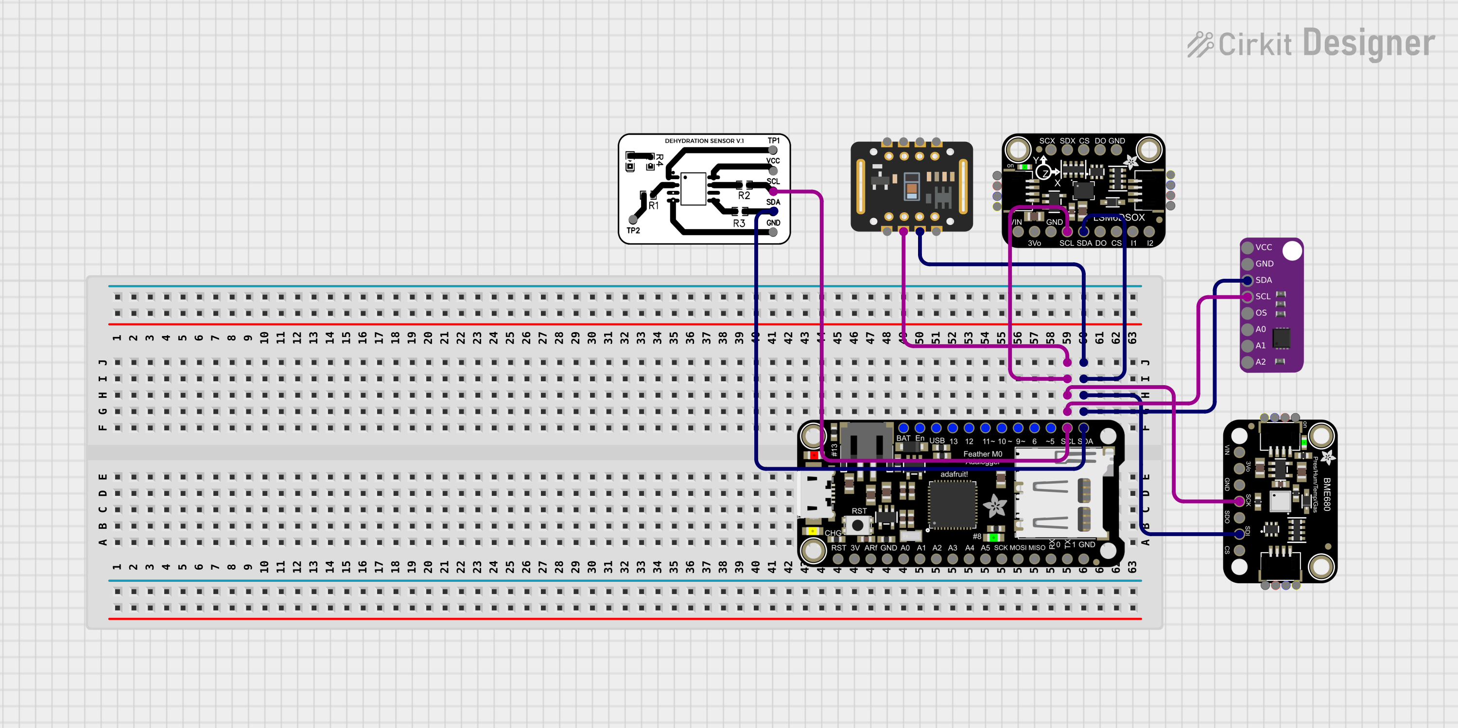

Explore Projects Built with Adafruit MAX98357A
Technical Specifications
Key Features
- Amplifier Type: Class D
- Output Power: 3.2W into 4Ω at 5V, 10% THD; 1.6W into 8Ω at 3.3V, 10% THD
- Audio Input: Digital I2S
- Supply Voltage: 2.7V to 5.5V
- PSRR: -77 dB
- Efficiency: Up to 93%
- No MCLK required
- Supported Sample Rates: 8kHz to 96kHz
- Built-in Click and Pop Noise Reduction
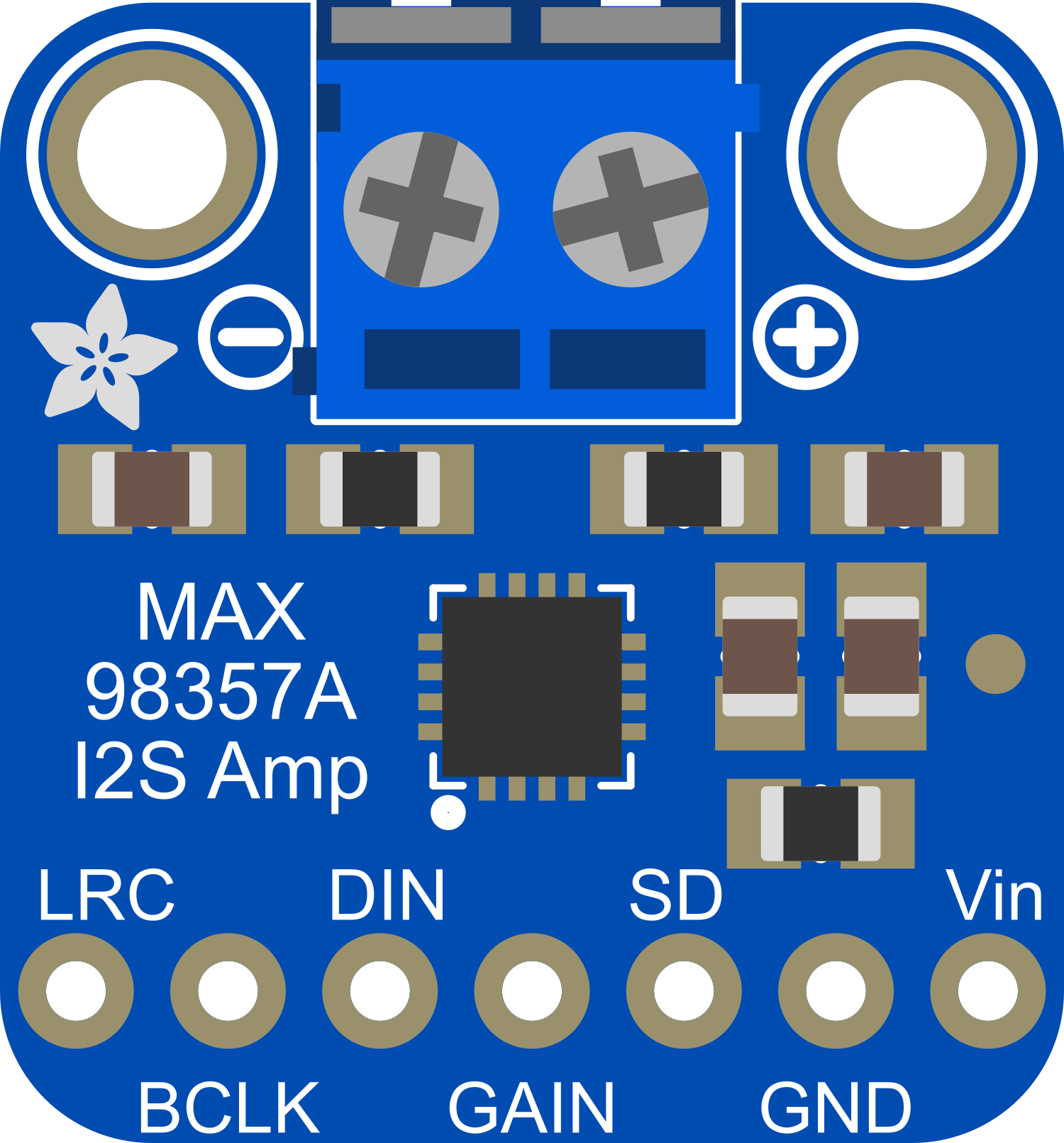
Pin Configuration and Descriptions
| Pin Number | Pin Name | Description |
|---|---|---|
| 1 | LRC | Left/Right Clock |
| 2 | BCLK | Bit Clock |
| 3 | DIN | Digital Audio Input |
| 4 | GND | Ground |
| 5 | Vin | Supply Voltage (2.7V to 5.5V) |
| 6 | GAIN | Gain Selection Pin |
| 7 | SD | Shutdown Pin |
| 8 | SPK+ | Speaker Output Positive |
| 9 | SPK- | Speaker Output Negative |
Usage Instructions
Connecting to a Circuit
- Power Supply: Connect the Vin pin to a 2.7V to 5.5V power supply and the GND pin to the ground of your system.
- Audio Input: Connect the I2S data input (DIN), bit clock (BCLK), and left/right clock (LRC) to the corresponding I2S output pins of your audio source.
- Speaker Output: Connect a speaker to the SPK+ and SPK- pins. Ensure the speaker's impedance and power ratings are compatible with the amplifier's output.
- Gain Setting: The GAIN pin can be connected to Vin, GND, or left floating to select between different gain settings (9dB, 12dB, 15dB).
- Shutdown Control: The SD pin can be driven low to put the amplifier into a low-power shutdown mode. Pull it high to resume normal operation.
Best Practices
- Use a power supply that can deliver sufficient current for the desired output power.
- Keep the audio signal paths as short as possible to minimize noise and interference.
- Ensure proper heat dissipation if operating the amplifier near its maximum output power.
- Use a decoupling capacitor close to the Vin pin to filter out power supply noise.
Example Code for Arduino UNO
#include <Wire.h>
#include <Adafruit_I2S.h>
#include <Adafruit_MAX98357A.h>

// Create an instance of the I2S audio object
Adafruit_I2S i2s = Adafruit_I2S();

// Create an instance of the MAX98357A amplifier object
Adafruit_MAX98357A amp = Adafruit_MAX98357A();

void setup() {
  Serial.begin(115200);

  // Initialize I2S at the desired sample rate
  if (!i2s.begin(I2S_16_BIT, 22050)) {
    Serial.println("Failed to initialize I2S!");
    while (1);
  }

  // Enable the amplifier
  amp.enable();
}

void loop() {
  // Your audio processing code goes here
  // For example, you can play audio data using i2s.write()
}
Troubleshooting and FAQs
Common Issues
- No Sound Output: Ensure all connections are secure and the speaker is functional. Check that the I2S data is being sent correctly.
- Distorted Sound: This may be due to an overdriven input signal or power supply issues. Ensure the input signal level is appropriate and the power supply is stable and within the specified voltage range.
- Intermittent Sound: Check for loose connections or cold solder joints. Also, ensure that the SD pin is not being inadvertently driven low.
FAQs
Q: Can I use the MAX98357A with a microcontroller other than the Raspberry Pi? A: Yes, the MAX98357A can be used with any microcontroller that provides an I2S output.
Q: What speakers can I use with the MAX98357A? A: You can use any speaker with an impedance of 4Ω to 8Ω and power handling compatible with the amplifier's output.
Q: How do I change the gain on the MAX98357A? A: The gain can be adjusted by connecting the GAIN pin to Vin, GND, or leaving it floating.
Q: Can I power the MAX98357A with a 3.3V supply? A: Yes, the MAX98357A can operate with a supply voltage as low as 2.7V, but the output power will be reduced compared to a 5V supply.
For further assistance, consult the Adafruit MAX98357A datasheet and the support forums for the development board you are using.