
How to Use B-G431B-ESC1: Examples, Pinouts, and Specs
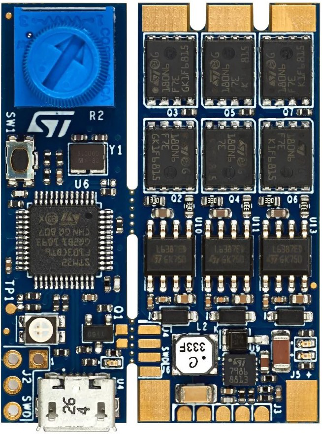
 Design with B-G431B-ESC1 in Cirkit Designer
Introduction
The B-G431B-ESC1 is a compact and versatile electronic speed controller (ESC) developed by STM32. It is specifically designed for controlling brushless DC (BLDC) motors and permanent magnet synchronous motors (PMSMs). This ESC leverages advanced control algorithms, such as field-oriented control (FOC), to deliver precise motor management and efficient power delivery. Its compact design and robust features make it ideal for applications in robotics, drones, electric vehicles, and industrial automation.
Explore Projects Built with B-G431B-ESC1
 Open Project in Cirkit Designer
 Open Project in Cirkit Designer
 Open Project in Cirkit Designer
 Open Project in Cirkit Designer
Explore Projects Built with B-G431B-ESC1
Open Project in Cirkit DesignerOpen Project in Cirkit DesignerOpen Project in Cirkit DesignerOpen Project in Cirkit DesignerCommon Applications
- Drones and UAVs: Provides smooth and efficient motor control for stable flight.
- Robotics: Enables precise motor control for robotic arms, mobile robots, and other systems.
- Electric Vehicles: Used in small-scale EVs for efficient motor management.
- Industrial Automation: Powers motors in conveyor belts, pumps, and other automated systems.
Technical Specifications
Key Technical Details
| Parameter | Value |
|---|---|
| Microcontroller | STM32G431CBU6 (ARM Cortex-M4, 170 MHz, 32-bit) |
| Input Voltage Range | 5.5 V to 35 V |
| Maximum Current | 40 A (continuous) |
| Motor Types Supported | Brushless DC (BLDC), Permanent Magnet Synchronous Motors (PMSM) |
| Control Algorithms | Field-Oriented Control (FOC), 6-step control |
| Communication Interfaces | UART, CAN, PWM, and I2C |
| Dimensions | 50 mm x 50 mm x 15 mm |
| Operating Temperature | -40°C to +85°C |
| Programming Interface | ST-LINK/V2 or ST-LINK/V3 |
Pin Configuration and Descriptions
| Pin Name | Type | Description |
|---|---|---|
| VIN | Power Input | Main power supply input (5.5 V to 35 V). |
| GND | Power Ground | Ground connection for the power supply. |
| MOTOR_A | Output | Phase A connection for the motor. |
| MOTOR_B | Output | Phase B connection for the motor. |
| MOTOR_C | Output | Phase C connection for the motor. |
| UART_TX | Communication | UART transmit pin for communication with external devices. |
| UART_RX | Communication | UART receive pin for communication with external devices. |
| PWM_IN | Input | PWM signal input for motor speed control. |
| CAN_H | Communication | CAN bus high signal for communication. |
| CAN_L | Communication | CAN bus low signal for communication. |
| I2C_SCL | Communication | I2C clock line for communication. |
| I2C_SDA | Communication | I2C data line for communication. |
| ST-LINK | Debugging | Debugging and programming interface (SWD). |
Usage Instructions
How to Use the B-G431B-ESC1 in a Circuit
- Power Supply: Connect a DC power source (5.5 V to 35 V) to the VIN and GND pins. Ensure the power supply can handle the current requirements of your motor.
- Motor Connection: Connect the three motor phases (A, B, C) to the MOTOR_A, MOTOR_B, and MOTOR_C pins, respectively.
- Control Signal: Use one of the supported communication interfaces (e.g., PWM, UART, CAN, or I2C) to send control signals to the ESC.
- Programming: If custom firmware is required, connect an ST-LINK programmer to the ST-LINK interface for programming and debugging.
- Startup: Power on the ESC and initialize the motor control algorithm (e.g., FOC) using the provided STM32 firmware or your custom code.
Important Considerations
- Heat Dissipation: Ensure proper cooling or heat sinking, especially when operating at high currents.
- Motor Compatibility: Verify that the motor's voltage and current ratings are within the ESC's supported range.
- Firmware Updates: Use STM32CubeIDE or STM32CubeProgrammer to update the firmware for optimal performance.
- Signal Integrity: Use shielded cables for communication lines to minimize noise in high-power environments.
Example Code for Arduino UNO (PWM Control)
The B-G431B-ESC1 can be controlled using a PWM signal from an Arduino UNO. Below is an example code snippet:
// Example: Controlling the B-G431B-ESC1 using PWM from Arduino UNO

const int pwmPin = 9; // PWM output pin connected to the ESC's PWM_IN pin

void setup() {
  pinMode(pwmPin, OUTPUT); // Set the PWM pin as an output
  analogWrite(pwmPin, 0);  // Initialize PWM signal to 0 (motor off)
}

void loop() {
  // Gradually increase motor speed
  for (int speed = 0; speed <= 255; speed++) {
    analogWrite(pwmPin, speed); // Send PWM signal (0-255 corresponds to 0-100%)
    delay(20);                  // Delay for smooth acceleration
  }

  delay(2000); // Run motor at full speed for 2 seconds

  // Gradually decrease motor speed
  for (int speed = 255; speed >= 0; speed--) {
    analogWrite(pwmPin, speed); // Decrease PWM signal
    delay(20);                  // Delay for smooth deceleration
  }

  delay(2000); // Wait for 2 seconds before repeating
}
Troubleshooting and FAQs
Common Issues and Solutions
Motor Does Not Spin:
- Cause: Incorrect wiring or insufficient power supply.
- Solution: Double-check all connections and ensure the power supply meets the voltage and current requirements.
Overheating:
- Cause: Prolonged operation at high currents without proper cooling.
- Solution: Add a heat sink or active cooling (e.g., a fan) to the ESC.
Communication Failure:
- Cause: Noise or incorrect configuration of communication interfaces.
- Solution: Use shielded cables and verify the communication settings (baud rate, protocol, etc.).
Motor Vibrates but Does Not Rotate:
- Cause: Incorrect motor phase connections or control algorithm settings.
- Solution: Verify the motor phase wiring and ensure the correct control algorithm (e.g., FOC) is selected.
FAQs
Q: Can I use the B-G431B-ESC1 with brushed DC motors?
A: No, the ESC is designed specifically for brushless DC (BLDC) and PMSM motors.Q: How do I update the firmware?
A: Use the STM32CubeProgrammer tool with an ST-LINK programmer to flash the latest firmware.Q: What is the maximum PWM frequency supported?
A: The ESC supports PWM frequencies up to 20 kHz.Q: Can I use the ESC with a 3.3 V logic microcontroller?
A: Yes, the communication interfaces are compatible with 3.3 V logic levels.
This concludes the documentation for the B-G431B-ESC1. For further details, refer to the official STM32 datasheet and user manual.