How to Use BLDC Motor Driver: Examples, Pinouts, and Specs
Introduction
The BLD-305S is a high-performance Brushless DC (BLDC) Motor Driver manufactured by StepperOnline. This driver is designed to control the operation of BLDC motors by regulating the voltage and current supplied to the motor windings. It enables precise speed, torque, and position control, making it ideal for a wide range of applications.
Explore Projects Built with BLDC Motor Driver

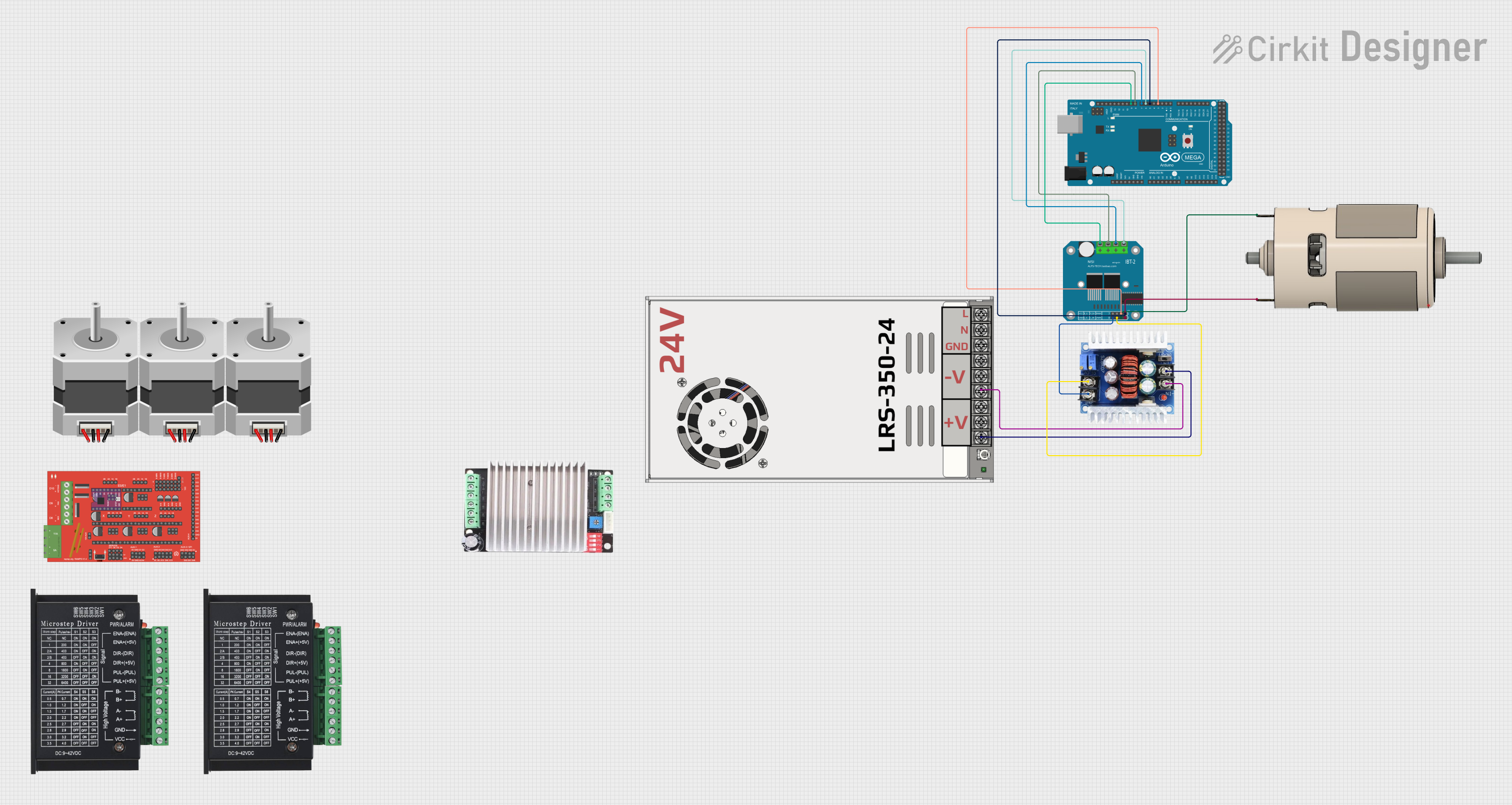
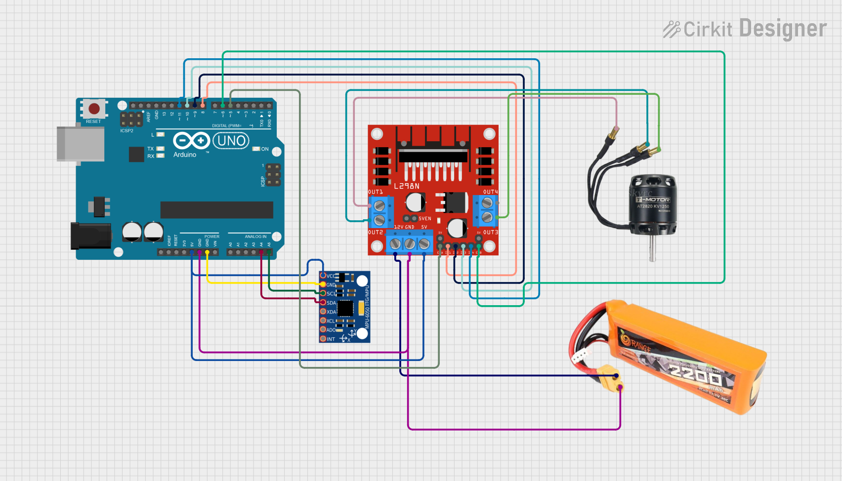

Explore Projects Built with BLDC Motor Driver
Common Applications and Use Cases
- Industrial automation and robotics
- CNC machines and 3D printers
- Electric vehicles and drones
- HVAC systems and pumps
- Conveyor belts and material handling systems
Technical Specifications
The BLD-305S is engineered to deliver reliable performance with the following key specifications:
| Parameter | Value |
|---|---|
| Input Voltage Range | 20V to 50V DC |
| Continuous Output Current | 5A |
| Peak Output Current | 15A |
| Control Signal Input | PWM, Analog Voltage, or Direction |
| Speed Range | 0 to 20,000 RPM |
| Operating Temperature | -10°C to +45°C |
| Dimensions | 118mm x 75mm x 33mm |
| Weight | 300g |
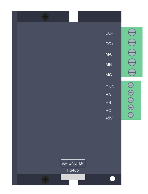
Pin Configuration and Descriptions
The BLD-305S features a user-friendly interface with the following pin configuration:
Power and Motor Connections
| Pin Name | Description |
|---|---|
| V+ | Positive DC power input (20-50V) |
| GND | Ground connection |
| U | Motor phase U connection |
| V | Motor phase V connection |
| W | Motor phase W connection |
Control Signal Connections
| Pin Name | Description |
|---|---|
| EN | Enable input (active high) |
| PWM | PWM signal input for speed control |
| DIR | Direction control input (high/low for CW/CCW) |
| FG | Frequency generator output (motor speed feedback) |
| VR | Analog voltage input for speed control (0-5V) |
Usage Instructions
How to Use the Component in a Circuit
- Power Supply: Connect a DC power supply (20-50V) to the
V+andGNDpins. Ensure the power supply can provide sufficient current for your motor's requirements. - Motor Connection: Connect the three motor windings to the
U,V, andWpins. Ensure the connections match the motor's datasheet. - Control Signals:
- For PWM control, connect a PWM signal to the
PWMpin and set the desired duty cycle. - For direction control, connect a digital signal to the
DIRpin (high for clockwise, low for counterclockwise). - Optionally, use the
VRpin for analog voltage-based speed control (0-5V corresponds to 0-100% speed).
- For PWM control, connect a PWM signal to the
- Enable the Driver: Apply a high signal to the
ENpin to enable the driver.
Important Considerations and Best Practices
- Heat Dissipation: The driver may generate heat during operation. Use a heatsink or active cooling if necessary.
- Current Limiting: Ensure the motor's current does not exceed the driver's rated continuous or peak current.
- Wiring: Use appropriately rated wires for power and motor connections to avoid voltage drops or overheating.
- Startup Sequence: Always enable the driver (
ENpin) after connecting the motor and control signals to prevent damage.
Example: Using the BLD-305S with an Arduino UNO
Below is an example of how to control the BLD-305S using an Arduino UNO with PWM and direction control:
// Define pin connections
const int pwmPin = 9;  // PWM signal output
const int dirPin = 8;  // Direction control
const int enPin = 7;   // Enable pin

void setup() {
  // Set pin modes
  pinMode(pwmPin, OUTPUT);
  pinMode(dirPin, OUTPUT);
  pinMode(enPin, OUTPUT);

  // Enable the motor driver
  digitalWrite(enPin, HIGH);

  // Set initial direction to clockwise
  digitalWrite(dirPin, HIGH);
}

void loop() {
  // Set motor speed using PWM (0-255 corresponds to 0-100% duty cycle)
  analogWrite(pwmPin, 128);  // 50% speed

  delay(5000);  // Run for 5 seconds

  // Change direction to counterclockwise
  digitalWrite(dirPin, LOW);

  delay(5000);  // Run for another 5 seconds
}
Troubleshooting and FAQs
Common Issues and Solutions
Motor Does Not Spin:
- Verify that the
ENpin is set to HIGH. - Check the power supply voltage and ensure it is within the 20-50V range.
- Ensure the motor windings are correctly connected to the
U,V, andWpins.
- Verify that the
Motor Spins in the Wrong Direction:
- Reverse the signal on the
DIRpin (HIGH for clockwise, LOW for counterclockwise). - Verify the motor's wiring and phase sequence.
- Reverse the signal on the
Driver Overheats:
- Ensure proper ventilation or use a heatsink.
- Check that the motor's current does not exceed the driver's rated current.
No Speed Control:
- Verify the PWM signal is being generated correctly.
- If using analog voltage control, ensure the
VRpin receives a 0-5V signal.
FAQs
Q: Can I use the BLD-305S with a 12V motor?
A: No, the minimum input voltage for the BLD-305S is 20V. Using a 12V motor may result in improper operation or damage.
Q: Does the driver support closed-loop control?
A: The BLD-305S provides a frequency generator (FG) output for speed feedback, which can be used in a closed-loop control system with an external controller.
Q: Can I control the driver with a Raspberry Pi?
A: Yes, the BLD-305S can be controlled using a Raspberry Pi's GPIO pins for PWM and direction signals. Ensure proper voltage level shifting if needed.