How to Use Insulated Ultrafast Rectifier Module: Examples, Pinouts, and Specs
Introduction
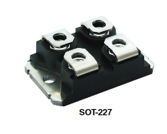
The Insulated Ultrafast Rectifier Module (Part ID: VS-UFB80FA20) by VISHAY is a high-efficiency semiconductor device designed to convert alternating current (AC) to direct current (DC). This module is known for its fast switching speed and electrical insulation between the input and output, making it ideal for applications requiring high performance and reliability.
Explore Projects Built with Insulated Ultrafast Rectifier Module


Explore Projects Built with Insulated Ultrafast Rectifier Module
Common Applications and Use Cases
- Power Supplies: Used in switch-mode power supplies (SMPS) for efficient AC to DC conversion.
- Inverters: Essential in inverters for renewable energy systems like solar and wind power.
- Motor Drives: Utilized in motor drive circuits for industrial automation.
- Battery Chargers: Employed in high-efficiency battery charging systems.
- Telecommunications: Used in power rectification for telecom equipment.
Technical Specifications
Key Technical Details
| Parameter | Value |
|---|---|
| Maximum Repetitive Peak Reverse Voltage (V_RRM) | 200 V |
| Maximum Average Forward Current (I_F(AV)) | 80 A |
| Maximum Surge Current (I_FSM) | 800 A |
| Forward Voltage Drop (V_F) | 1.05 V at 80 A |
| Reverse Recovery Time (t_rr) | 25 ns |
| Operating Junction Temperature (T_j) | -55°C to +175°C |
| Insulation Voltage | 2500 V AC |
Pin Configuration and Descriptions
| Pin Number | Pin Name | Description |
|---|---|---|
| 1 | Anode 1 | Positive terminal for the first diode |
| 2 | Cathode 1 | Negative terminal for the first diode |
| 3 | Anode 2 | Positive terminal for the second diode |
| 4 | Cathode 2 | Negative terminal for the second diode |
Usage Instructions
How to Use the Component in a Circuit
- Identify the Pins: Ensure you correctly identify the anode and cathode pins using the pin configuration table.
- Connect to Power Source: Connect the anode to the positive side of the AC source and the cathode to the load or the positive side of the DC output.
- Heat Management: Use appropriate heat sinks to manage the heat dissipation, as the module can generate significant heat during operation.
- Insulation: Ensure proper insulation between the input and output to prevent electrical hazards.
Important Considerations and Best Practices
- Heat Dissipation: Always use a heat sink to manage thermal performance.
- Voltage Ratings: Do not exceed the maximum voltage and current ratings to avoid damage.
- Reverse Recovery: Consider the reverse recovery time in high-frequency applications to ensure efficient operation.
- Insulation: Maintain proper insulation to prevent electrical shorts and ensure safety.
Troubleshooting and FAQs
Common Issues Users Might Face
Overheating:
- Solution: Ensure proper heat sinking and ventilation. Check for any obstructions to airflow.
High Forward Voltage Drop:
- Solution: Verify the current rating and ensure it is within the specified limits. Check for any loose connections.
Slow Switching Speed:
- Solution: Ensure the reverse recovery time is suitable for your application. Consider using a snubber circuit to improve performance.
Electrical Short:
- Solution: Double-check the insulation between input and output. Inspect for any damaged insulation material.
FAQs
Q1: Can I use this rectifier module in a high-frequency application?
- A1: Yes, the module's fast switching speed and low reverse recovery time make it suitable for high-frequency applications.
Q2: What type of heat sink should I use?
- A2: Use a heat sink with a thermal resistance low enough to keep the junction temperature within safe limits. The exact type depends on your specific application and thermal requirements.
Q3: How do I ensure proper insulation?
- A3: Use high-quality insulating materials and ensure there is no direct electrical connection between the input and output.
Q4: Can this module be used with an Arduino UNO?
- A4: While the module itself is not directly interfaced with an Arduino, it can be part of a larger power supply circuit that powers the Arduino.
Example Code for Arduino UNO
Here is an example of how you might use the rectified DC output from the module to power an Arduino UNO:
// Example code to read a sensor value and print it to the Serial Monitor
// Ensure the rectified DC output is within the Arduino's operating voltage range

void setup() {
  Serial.begin(9600); // Initialize serial communication at 9600 baud
}

void loop() {
  int sensorValue = analogRead(A0); // Read the sensor value from analog pin A0
  Serial.println(sensorValue); // Print the sensor value to the Serial Monitor
  delay(1000); // Wait for 1 second before repeating the loop
}
Note: Ensure the rectified DC output is regulated to 5V before connecting it to the Arduino UNO.
This documentation provides a comprehensive overview of the Insulated Ultrafast Rectifier Module (VS-UFB80FA20) by VISHAY, including its technical specifications, usage instructions, and troubleshooting tips. Whether you are a beginner or an experienced user, this guide aims to help you effectively utilize this component in your electronic projects.