How to Use Arduino Leonardo: Examples, Pinouts, and Specs
Introduction
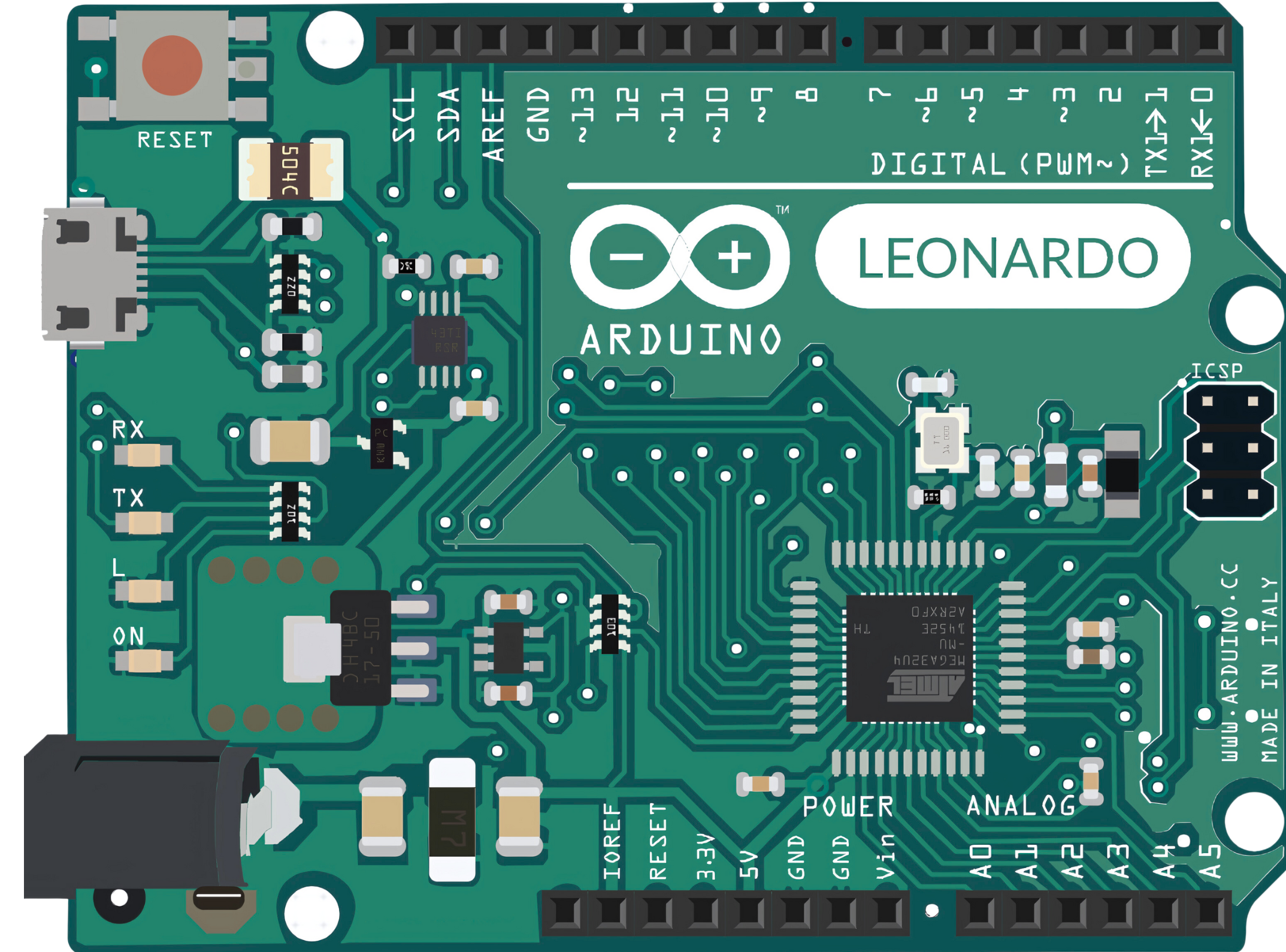
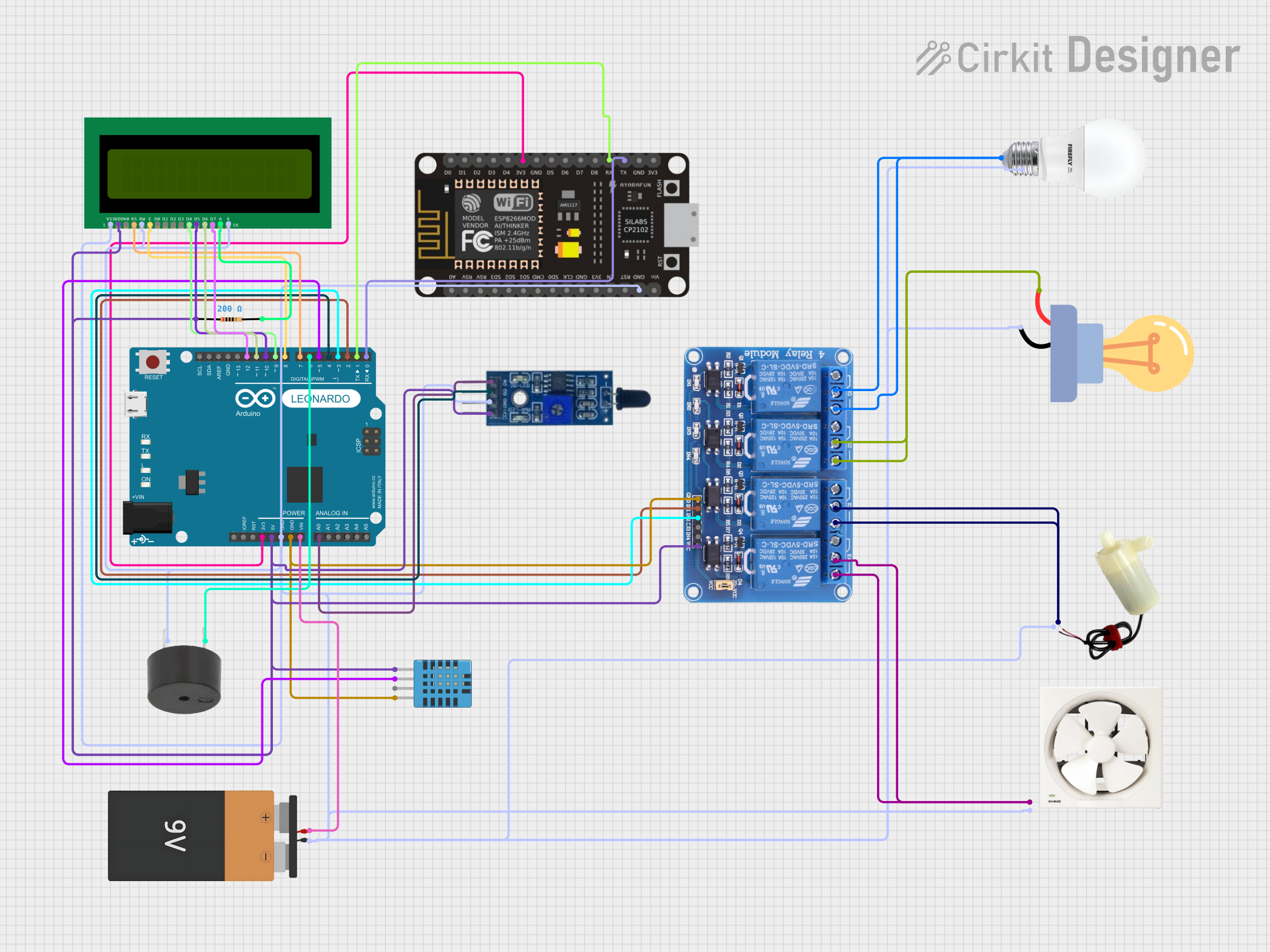
The Arduino Leonardo is a versatile microcontroller board based on the ATmega32u4. It is a member of the Arduino family and is notable for its built-in USB communication, eliminating the need for a secondary processor. This feature allows the Leonardo to appear as a mouse or keyboard to a connected computer, in addition to a virtual (CDC) serial / COM port. It is widely used in hobbyist and educational environments for creating interactive projects such as automation systems, robotics, and custom gaming controllers.
Explore Projects Built with Arduino Leonardo
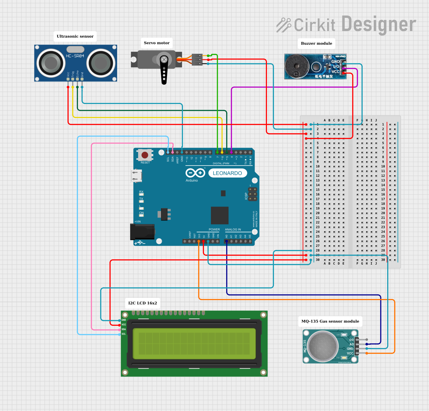
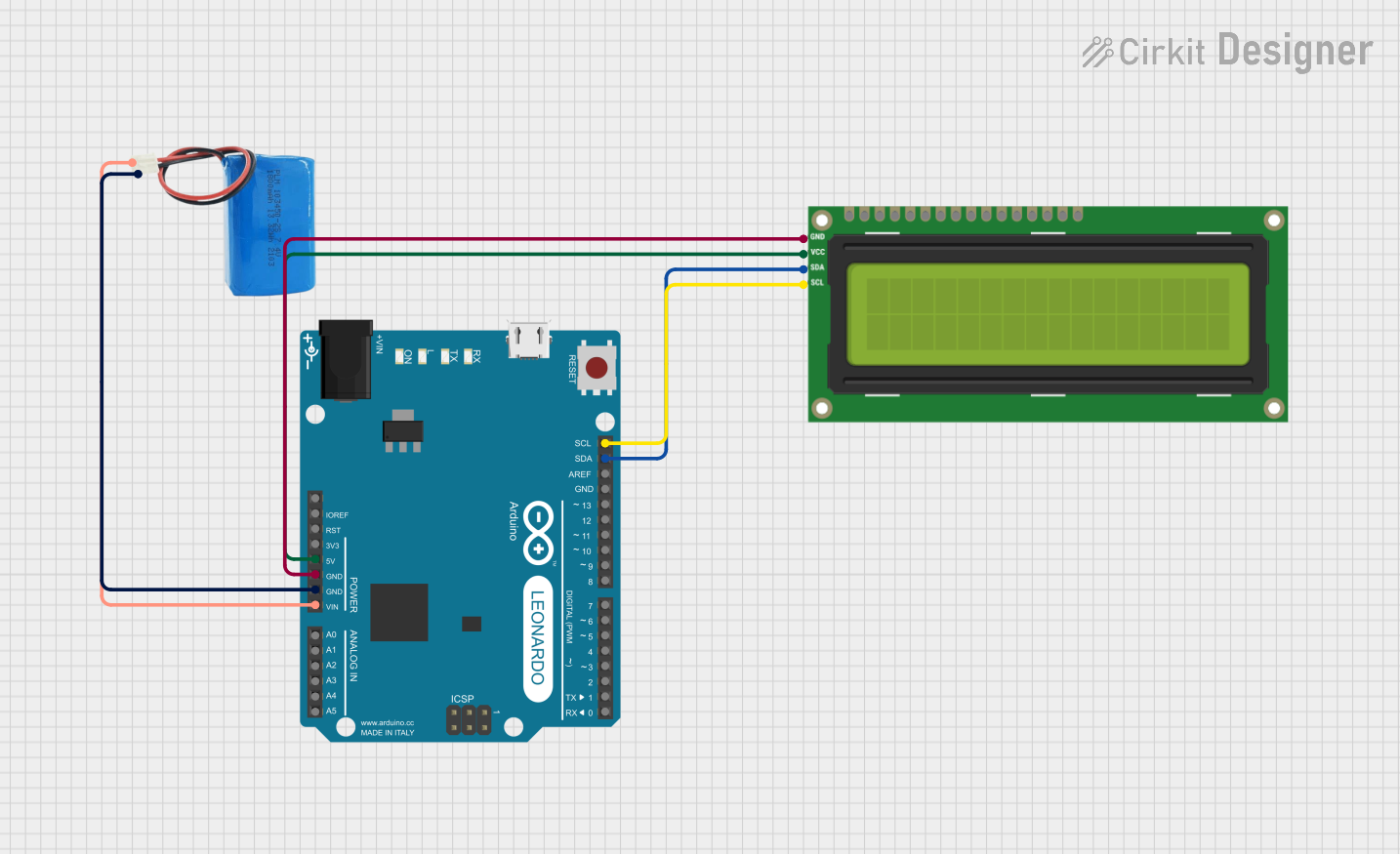
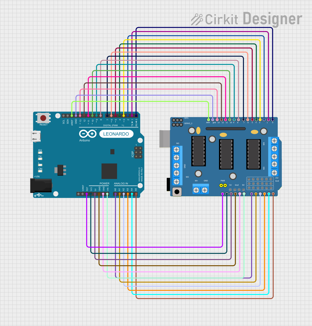
Explore Projects Built with Arduino Leonardo
Common Applications and Use Cases
- Human Interface Device (HID) projects
- Robotics and automation
- Educational purposes and DIY projects
- Prototyping IoT devices
- Custom keyboard or mouse
Technical Specifications
Key Technical Details
- Microcontroller: ATmega32u4
- Operating Voltage: 5V
- Input Voltage (recommended): 7-12V
- Input Voltage (limits): 6-20V
- Digital I/O Pins: 20 (of which 7 can be used as PWM outputs)
- Analog Input Pins: 12
- DC Current per I/O Pin: 40 mA
- DC Current for 3.3V Pin: 50 mA
- Flash Memory: 32 KB (ATmega32u4) of which 4 KB used by bootloader
- SRAM: 2.5 KB (ATmega32u4)
- EEPROM: 1 KB (ATmega32u4)
- Clock Speed: 16 MHz
Pin Configuration and Descriptions
| Pin Number | Function | Description |
|---|---|---|
| 1-14 | Digital I/O | Digital pins, can be used for input/output |
| 15-20 | Analog Inputs | Can also function as digital I/O |
| 3, 5, 6, 9, 10, 11, 13 | PWM Output | Pins capable of 8-bit PWM output |
| A0-A5 | Analog Inputs | Analog input pins, can also function as digital I/O |
| A6-A11 | Analog Inputs | Additional analog inputs on the ICSP header |
| RX/TX | Serial Comm. | Used for serial communication |
| RST | Reset | Used to reset the microcontroller |
| GND | Ground | Ground pins |
| 5V | Power | Regulated power supply for the microcontroller and components |
| 3.3V | Power | 3.3V supply generated by the onboard regulator |
| VIN | Voltage Input | Unregulated input voltage to the Arduino board |
Usage Instructions
How to Use the Component in a Circuit
Powering the Board:
- Connect a 7-12V power supply to the VIN and GND pins, or plug a USB cable into the board's USB port for power and communication.
Connecting I/O Devices:
- Digital devices can be connected to digital pins 0-20.
- Analog sensors can be connected to analog pins A0-A11.
- PWM devices can be connected to pins 3, 5, 6, 9, 10, 11, and 13.
Programming the Board:
- Connect the board to a computer using a USB cable.
- Use the Arduino IDE to write and upload sketches to the board.
Important Considerations and Best Practices
- Ensure that the power supply voltage does not exceed the recommended limits to prevent damage.
- When using PWM outputs, ensure that the connected devices are compatible with the 5V logic level.
- Use appropriate resistors or current-limiting devices to protect the I/O pins from excessive current.
- Avoid connecting devices that draw more than 40 mA from a single I/O pin.
- Always disconnect the power source before making or altering connections on the board.
Troubleshooting and FAQs
Common Issues Users Might Face
Board not recognized by the computer:
- Check the USB cable and port.
- Ensure the correct drivers are installed.
- Try resetting the board using the RST pin.
Sketch not uploading:
- Verify the correct board and port are selected in the Arduino IDE.
- Check for errors in the code.
- Ensure the bootloader is functioning correctly.
Unexpected behavior in circuits:
- Double-check wiring and connections.
- Ensure power supply is stable and within the recommended range.
- Verify that the code corresponds to the connected hardware.
Solutions and Tips for Troubleshooting
- Use the onboard LED connected to pin 13 to test basic sketches and ensure the board is functioning.
- Consult the Arduino forums and community for support and advice on specific issues.
- Review the official Arduino Leonardo documentation for additional troubleshooting tips.
Example Code for Arduino UNO
Here is a simple example of blinking an LED connected to pin 13 on the Arduino Leonardo:
// Define the LED pin
const int ledPin = 13;

// the setup routine runs once when you press reset:
void setup() {
  // initialize the digital pin as an output.
  pinMode(ledPin, OUTPUT);
}

// the loop routine runs over and over again forever:
void loop() {
  digitalWrite(ledPin, HIGH);   // turn the LED on (HIGH is the voltage level)
  delay(1000);                  // wait for a second
  digitalWrite(ledPin, LOW);    // turn the LED off by making the voltage LOW
  delay(1000);                  // wait for a second
}
This code will blink the onboard LED on the Arduino Leonardo, which is a great way to test if your setup is working correctly. Remember to select "Arduino Leonardo" from the Tools > Board menu in the Arduino IDE before uploading the sketch.