How to Use PH-4502C: Examples, Pinouts, and Specs
Introduction
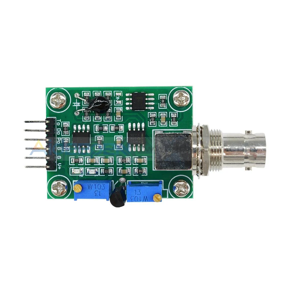
The PH-4502C is a high-performance, low-noise operational amplifier (op-amp) designed for precision signal processing applications. With its wide bandwidth and low distortion characteristics, this component is ideal for applications requiring high accuracy and minimal signal degradation. It is commonly used in audio amplification, instrumentation circuits, active filters, and other precision analog signal processing tasks.
Explore Projects Built with PH-4502C
Explore Projects Built with PH-4502C
Common Applications
- Audio signal amplification
- Instrumentation and measurement systems
- Active filters and oscillators
- Analog-to-digital converter (ADC) buffering
- Precision voltage reference circuits
Technical Specifications
The PH-4502C is designed to deliver reliable performance in demanding applications. Below are its key technical specifications:
| Parameter | Value |
|---|---|
| Supply Voltage Range | ±3V to ±18V |
| Input Offset Voltage | ≤ 1 mV |
| Input Bias Current | ≤ 50 nA |
| Gain Bandwidth Product | 10 MHz |
| Slew Rate | 0.5 V/µs |
| Output Voltage Swing | ±(Vcc - 1.5V) |
| Input Impedance | ≥ 10 MΩ |
| Output Impedance | ≤ 100 Ω |
| Operating Temperature | -40°C to +85°C |
| Package Type | DIP-8 or SOIC-8 |
Pin Configuration and Descriptions
The PH-4502C is typically available in an 8-pin Dual Inline Package (DIP-8) or Small Outline Integrated Circuit (SOIC-8). Below is the pinout and description:
| Pin Number | Pin Name | Description |
|---|---|---|
| 1 | Offset Null | Used for offset voltage adjustment (optional) |
| 2 | Inverting Input | Inverting input terminal (-) |
| 3 | Non-Inverting Input | Non-inverting input terminal (+) |
| 4 | V- (Negative Supply) | Negative power supply terminal |
| 5 | Offset Null | Used for offset voltage adjustment (optional) |
| 6 | Output | Output terminal for the amplified signal |
| 7 | V+ (Positive Supply) | Positive power supply terminal |
| 8 | NC (No Connection) | No internal connection (leave unconnected) |
Usage Instructions
The PH-4502C is straightforward to use in a variety of circuit configurations. Below are the steps and considerations for integrating it into your design:
Basic Circuit Configuration
- Power Supply: Connect the V+ pin (Pin 7) to the positive supply voltage and the V- pin (Pin 4) to the negative supply voltage. Ensure the supply voltage is within the specified range (±3V to ±18V).
- Input Connections: Connect the signal source to the inverting (Pin 2) or non-inverting input (Pin 3), depending on the desired configuration (e.g., inverting or non-inverting amplifier).
- Output Connection: Connect the output (Pin 6) to the load or the next stage of the circuit.
- Offset Adjustment (Optional): If precise offset voltage adjustment is required, connect a 10 kΩ potentiometer between the Offset Null pins (Pins 1 and 5) and tie the wiper to V+.
Important Considerations
- Bypass Capacitors: Place decoupling capacitors (e.g., 0.1 µF ceramic and 10 µF electrolytic) close to the power supply pins to minimize noise and ensure stable operation.
- Input Impedance: Use appropriate resistors to maintain high input impedance and avoid loading the signal source.
- Thermal Management: Ensure the component operates within the specified temperature range (-40°C to +85°C) to prevent performance degradation.
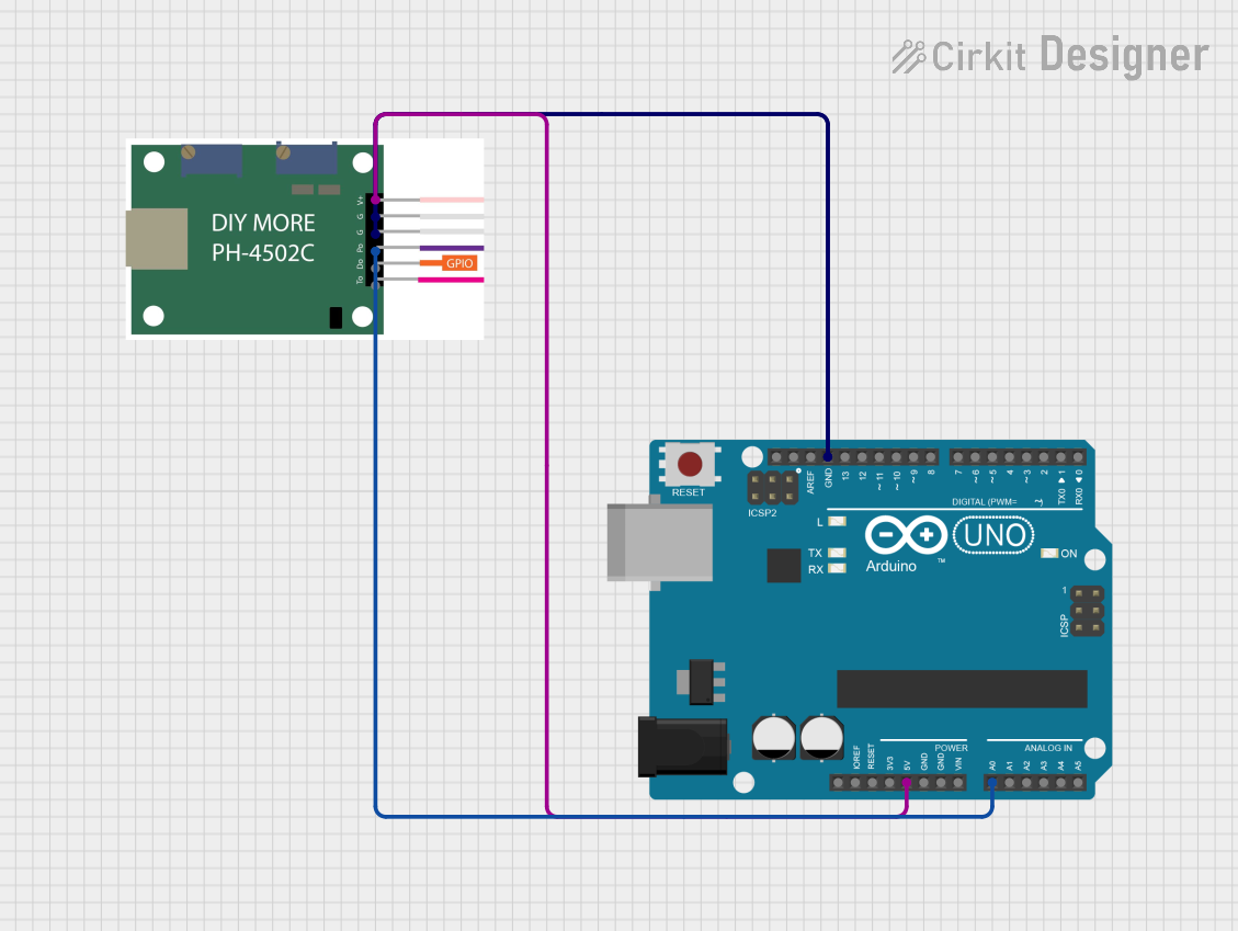
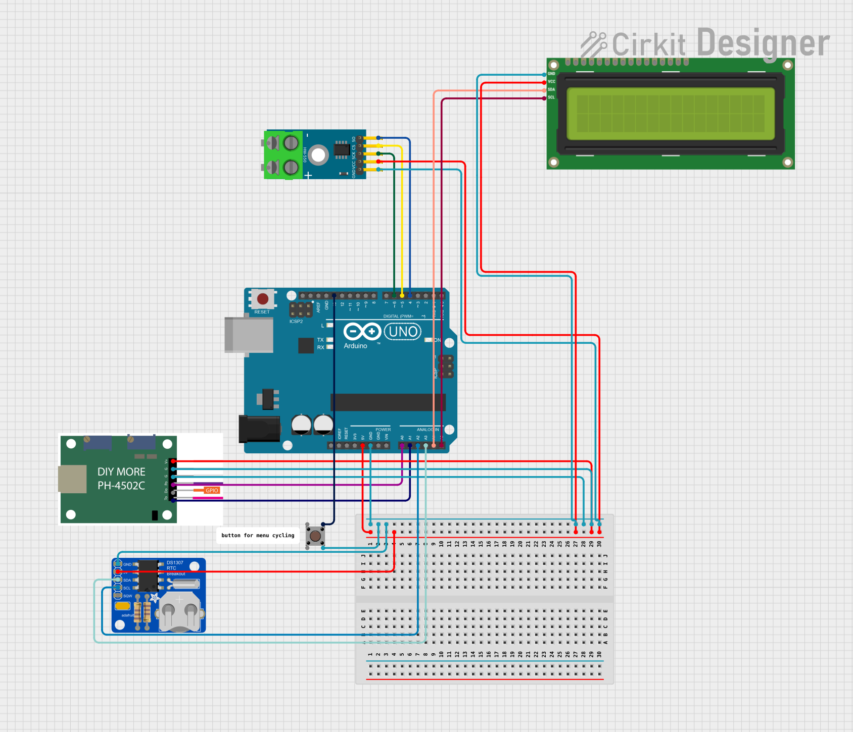
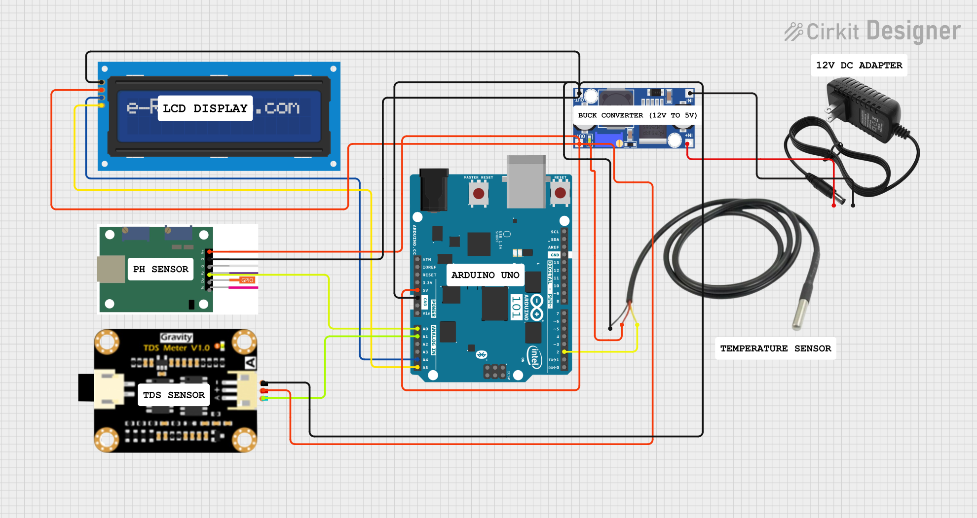
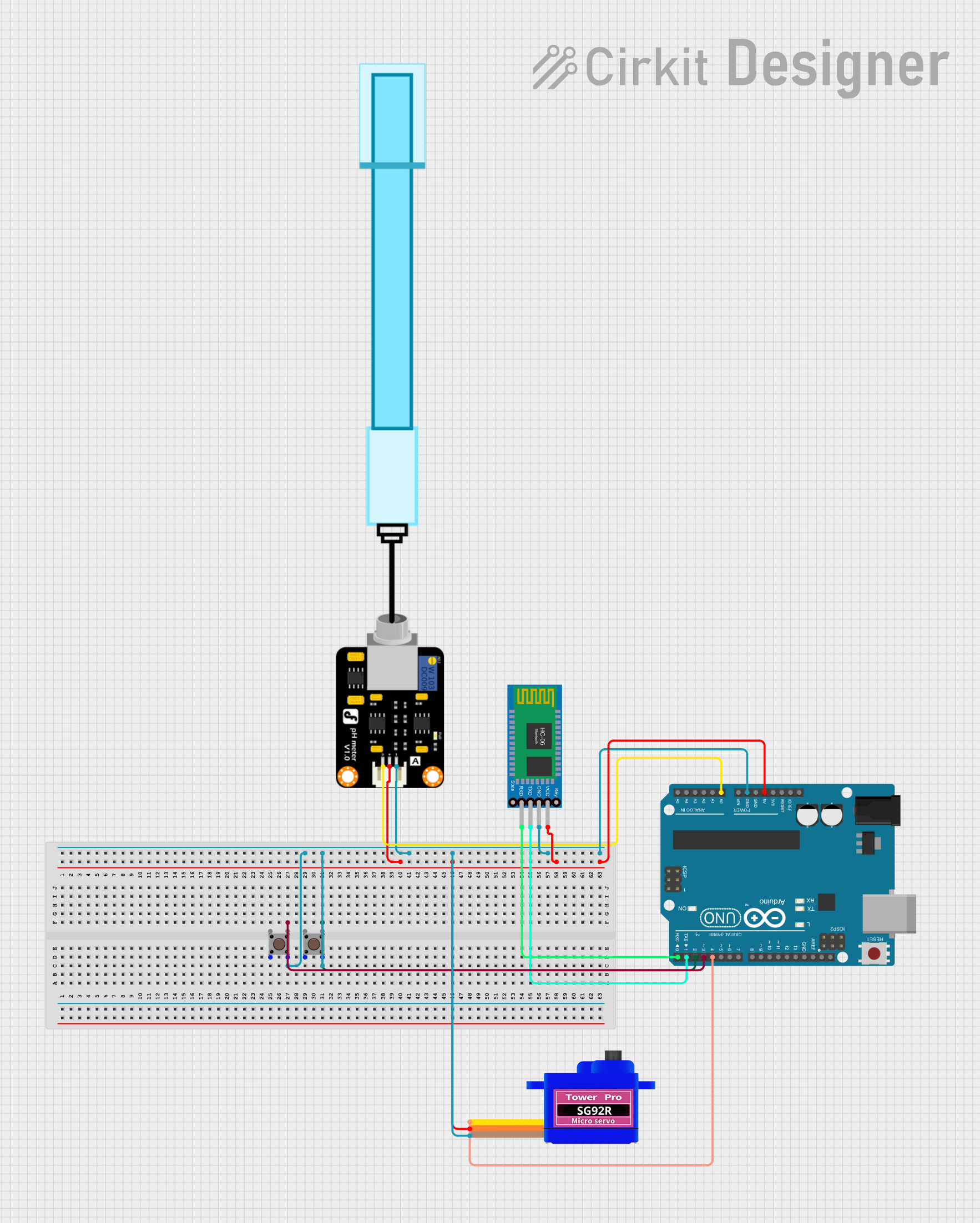
Example: Non-Inverting Amplifier Circuit with Arduino UNO
The PH-4502C can be used with an Arduino UNO for signal amplification. Below is an example circuit and code:
Circuit Description
- Connect the PH-4502C in a non-inverting amplifier configuration.
- The input signal is connected to the non-inverting input (Pin 3).
- The gain is set using two resistors, R1 and R2, where Gain = 1 + (R2 / R1).
- The amplified signal is fed to the Arduino's analog input pin (e.g., A0).
Arduino Code
// Arduino code to read the amplified signal from the PH-4502C
// and display the voltage on the serial monitor.

const int analogPin = A0; // Analog pin connected to PH-4502C output
float voltage = 0.0;      // Variable to store the measured voltage

void setup() {
  Serial.begin(9600); // Initialize serial communication at 9600 baud
}

void loop() {
  int sensorValue = analogRead(analogPin); // Read the analog input
  voltage = sensorValue * (5.0 / 1023.0);  // Convert ADC value to voltage
  Serial.print("Voltage: ");
  Serial.print(voltage, 2); // Print voltage with 2 decimal places
  Serial.println(" V");
  delay(500); // Wait for 500 ms before the next reading
}
Best Practices
- Use shielded cables for input signals to minimize noise interference.
- Avoid exceeding the maximum supply voltage to prevent damage to the component.
- For high-frequency applications, consider using a feedback capacitor to improve stability.
Troubleshooting and FAQs
Common Issues and Solutions
No Output Signal:
- Verify the power supply connections and ensure the voltage is within the specified range.
- Check the input signal and ensure it is properly connected to the input pins.
Distorted Output:
- Ensure the gain is not set too high, as this can cause clipping.
- Verify that the load impedance is not too low, which could overload the op-amp.
Excessive Noise:
- Add bypass capacitors close to the power supply pins.
- Use proper grounding techniques to minimize noise coupling.
Overheating:
- Check for excessive supply voltage or high ambient temperature.
- Ensure the op-amp is not driving a load beyond its current capability.
FAQs
Q1: Can the PH-4502C be used for single-supply operation?
A1: Yes, the PH-4502C can operate with a single supply voltage. In this case, connect V- (Pin 4) to ground and ensure the input and output signals are biased appropriately.
Q2: What is the maximum gain I can achieve with the PH-4502C?
A2: The maximum gain depends on the application and stability requirements. For most applications, gains up to 100 are achievable without significant stability issues.
Q3: Can I use the PH-4502C for high-frequency applications?
A3: The PH-4502C has a gain bandwidth product of 10 MHz, making it suitable for moderate-frequency applications. For higher frequencies, consider op-amps with a higher bandwidth.
Q4: How do I minimize offset voltage in my circuit?
A4: Use the Offset Null pins (Pins 1 and 5) with a potentiometer to adjust and minimize the offset voltage.
By following this documentation, you can effectively integrate the PH-4502C into your designs and troubleshoot common issues.