
How to Use LM2575 (TO220): Examples, Pinouts, and Specs
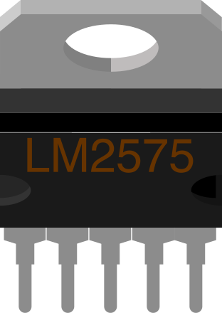
 Design with LM2575 (TO220) in Cirkit Designer
Introduction
The LM2575 is a step-down (buck) voltage regulator designed to provide a simple and efficient solution for power supply applications. It is capable of delivering up to 1A of output current with high efficiency and minimal external components. The LM2575 is available in both adjustable and fixed output voltage versions, making it versatile for a wide range of applications.
Explore Projects Built with LM2575 (TO220)
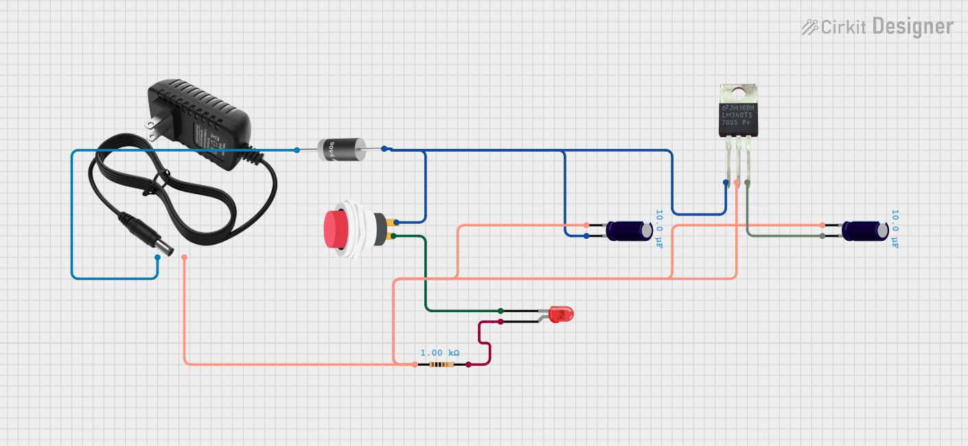 Open Project in Cirkit Designer
 Open Project in Cirkit Designer
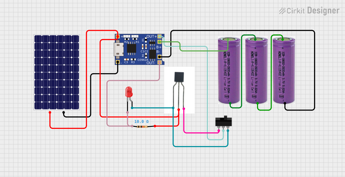 Open Project in Cirkit Designer
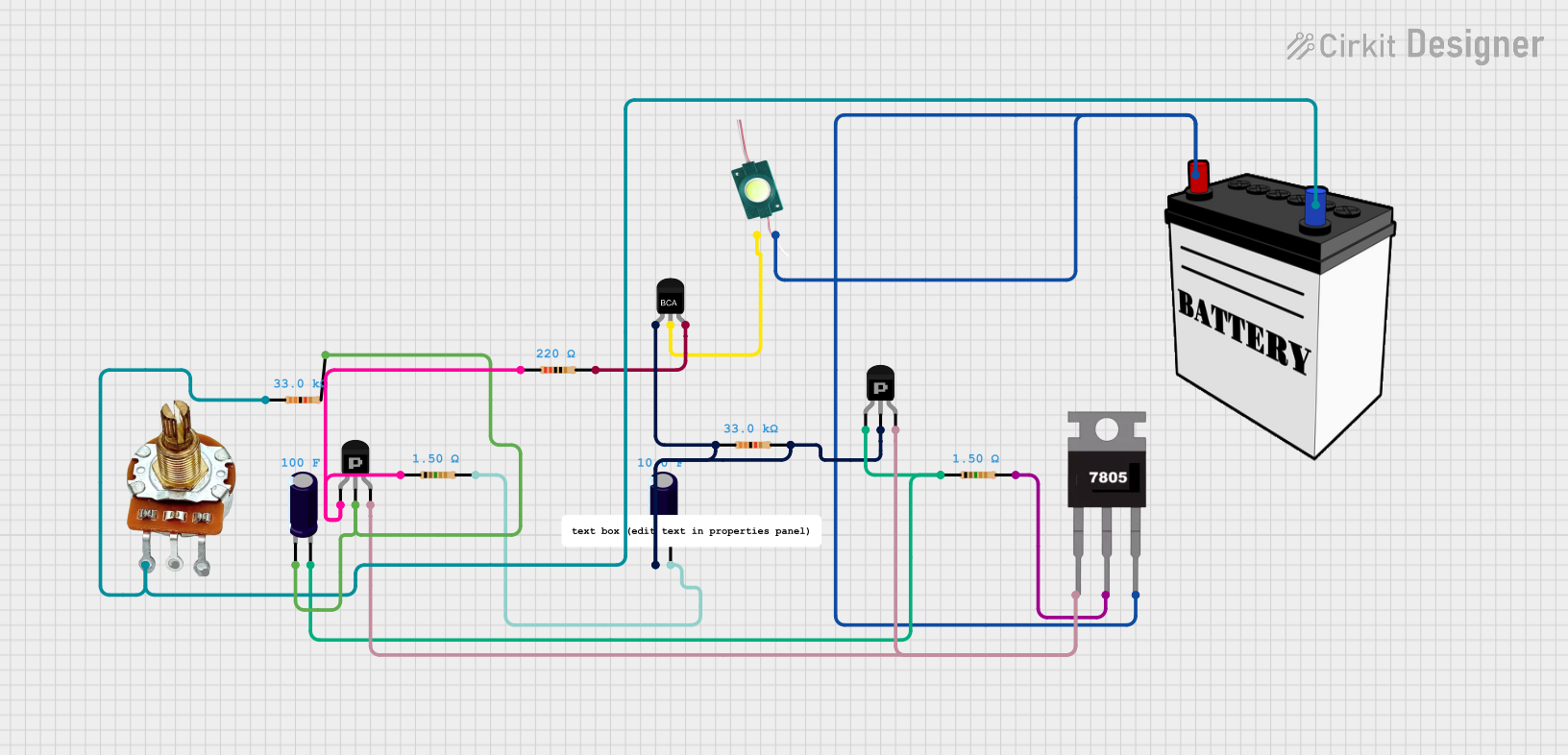 Open Project in Cirkit Designer
Explore Projects Built with LM2575 (TO220)
Open Project in Cirkit DesignerOpen Project in Cirkit DesignerOpen Project in Cirkit DesignerOpen Project in Cirkit DesignerCommon Applications
- DC-DC converters for battery-powered devices
- Industrial power supplies
- Automotive voltage regulation
- Embedded systems and microcontroller power supplies
- Consumer electronics
Technical Specifications
Key Technical Details
- Input Voltage Range: 4V to 40V
- Output Voltage:
- Adjustable version: 1.23V to 37V
- Fixed versions: 3.3V, 5V, 12V, 15V
- Output Current: Up to 1A
- Efficiency: Up to 90%
- Switching Frequency: 52 kHz (fixed)
- Dropout Voltage: Typically 1.5V at 1A load
- Thermal Shutdown: Built-in protection
- Current Limiting: Built-in protection
- Package: TO-220 (5-pin)
Pin Configuration and Descriptions
The LM2575 in the TO-220 package has 5 pins. The table below describes each pin:
| Pin Number | Pin Name | Description |
|---|---|---|
| 1 | VIN | Input voltage pin. Connect to the unregulated DC input voltage. |
| 2 | Output | Regulated output voltage pin. Connect to the load. |
| 3 | Ground | Ground pin. Connect to the system ground. |
| 4 | Feedback | Feedback pin. Used to set the output voltage (adjustable version only). |
| 5 | ON/OFF | Enable/disable pin. Logic high disables the regulator; logic low enables it. |
Usage Instructions
How to Use the LM2575 in a Circuit
- Input Voltage: Ensure the input voltage is within the range of 4V to 40V and at least 3V higher than the desired output voltage.
- Output Voltage:
- For fixed versions, connect the output pin directly to the load.
- For the adjustable version, use a resistor divider network connected to the feedback pin to set the desired output voltage.
- Inductor Selection: Choose an inductor with a current rating of at least 1.2 times the maximum load current and a value recommended in the datasheet for your output voltage.
- Capacitors:
- Use a low-ESR electrolytic capacitor on the input (e.g., 100 µF) to stabilize the input voltage.
- Use a low-ESR electrolytic capacitor on the output (e.g., 330 µF) to reduce output ripple.
- Diode Selection: Use a Schottky diode (e.g., 1N5819) with a current rating equal to or greater than the load current and a reverse voltage rating higher than the input voltage.
- ON/OFF Pin: If not used, connect the ON/OFF pin to ground to enable the regulator.
Example Circuit
Below is a basic circuit for the LM2575 adjustable version:
VIN (12V) ----+----+--------------------+
              |    |                    |
             [C1] [D1]                 |
              |    |                   |
              +----+                   |
              |                        |
             [L1]                      |
              |                        |
              +----+----+              |
              |    |    |              |
             [R1] [R2] [C2]            |
              |    |    |              |
              +----+----+--------------+
- C1: Input capacitor (e.g., 100 µF, 50V)
- D1: Schottky diode (e.g., 1N5819)
- L1: Inductor (e.g., 330 µH)
- R1, R2: Resistor divider to set output voltage
- C2: Output capacitor (e.g., 330 µF, 25V)
Arduino UNO Example Code
The LM2575 can be used to power an Arduino UNO. Below is an example code to monitor the output voltage using the Arduino's ADC:
// Define the analog pin connected to the LM2575 output
const int voltagePin = A0;

// Reference voltage for ADC (5V for Arduino UNO)
const float referenceVoltage = 5.0;

// ADC resolution (10-bit for Arduino UNO)
const int adcResolution = 1024;

void setup() {
  Serial.begin(9600); // Initialize serial communication
}

void loop() {
  int adcValue = analogRead(voltagePin); // Read the ADC value
  float outputVoltage = (adcValue * referenceVoltage) / adcResolution;

  // Print the output voltage to the Serial Monitor
  Serial.print("Output Voltage: ");
  Serial.print(outputVoltage);
  Serial.println(" V");

  delay(1000); // Wait for 1 second before the next reading
}
Important Considerations
- Always use low-ESR capacitors to minimize output ripple.
- Ensure proper heat dissipation by using a heatsink if the regulator operates at high currents.
- Avoid exceeding the maximum input voltage (40V) or output current (1A) to prevent damage.
Troubleshooting and FAQs
Common Issues and Solutions
Output Voltage is Incorrect:
- Check the resistor divider network (for adjustable versions).
- Verify the input voltage is at least 3V higher than the desired output voltage.
- Ensure the feedback pin is properly connected.
Excessive Heat:
- Use a heatsink to improve thermal dissipation.
- Check for excessive load current or input voltage.
High Output Ripple:
- Use low-ESR capacitors on the input and output.
- Verify the inductor value matches the recommended specifications.
No Output Voltage:
- Ensure the ON/OFF pin is connected to ground (logic low).
- Check all connections and components for proper placement.
FAQs
Q1: Can the LM2575 be used for negative voltage regulation?
A1: No, the LM2575 is designed for positive voltage regulation only. For negative voltages, consider using a different regulator.
Q2: What is the maximum efficiency of the LM2575?
A2: The LM2575 can achieve efficiencies of up to 90%, depending on the input and output voltage conditions.
Q3: Can I use the LM2575 without a heatsink?
A3: Yes, but only if the load current is low and the input-output voltage difference is minimal. For higher currents, a heatsink is recommended.
Q4: Is the LM2575 suitable for powering microcontrollers?
A4: Yes, the LM2575 is ideal for powering microcontrollers like Arduino, as it provides a stable and efficient power supply.