
How to Use EPW6 2.4GHz ELRS PWM Receiver: Examples, Pinouts, and Specs
 Design with EPW6 2.4GHz ELRS PWM Receiver in Cirkit Designer
Introduction
The EPW6 2.4GHz ELRS PWM Receiver by Happy Model is a compact and versatile receiver designed for remote control systems. It operates at a 2.4GHz frequency and is compatible with the ExpressLRS (ELRS) protocol, offering low-latency and long-range communication. The receiver outputs PWM (Pulse Width Modulation) signals, making it ideal for controlling servos, electronic speed controllers (ESCs), and other devices in RC (remote control) applications.
Explore Projects Built with EPW6 2.4GHz ELRS PWM Receiver
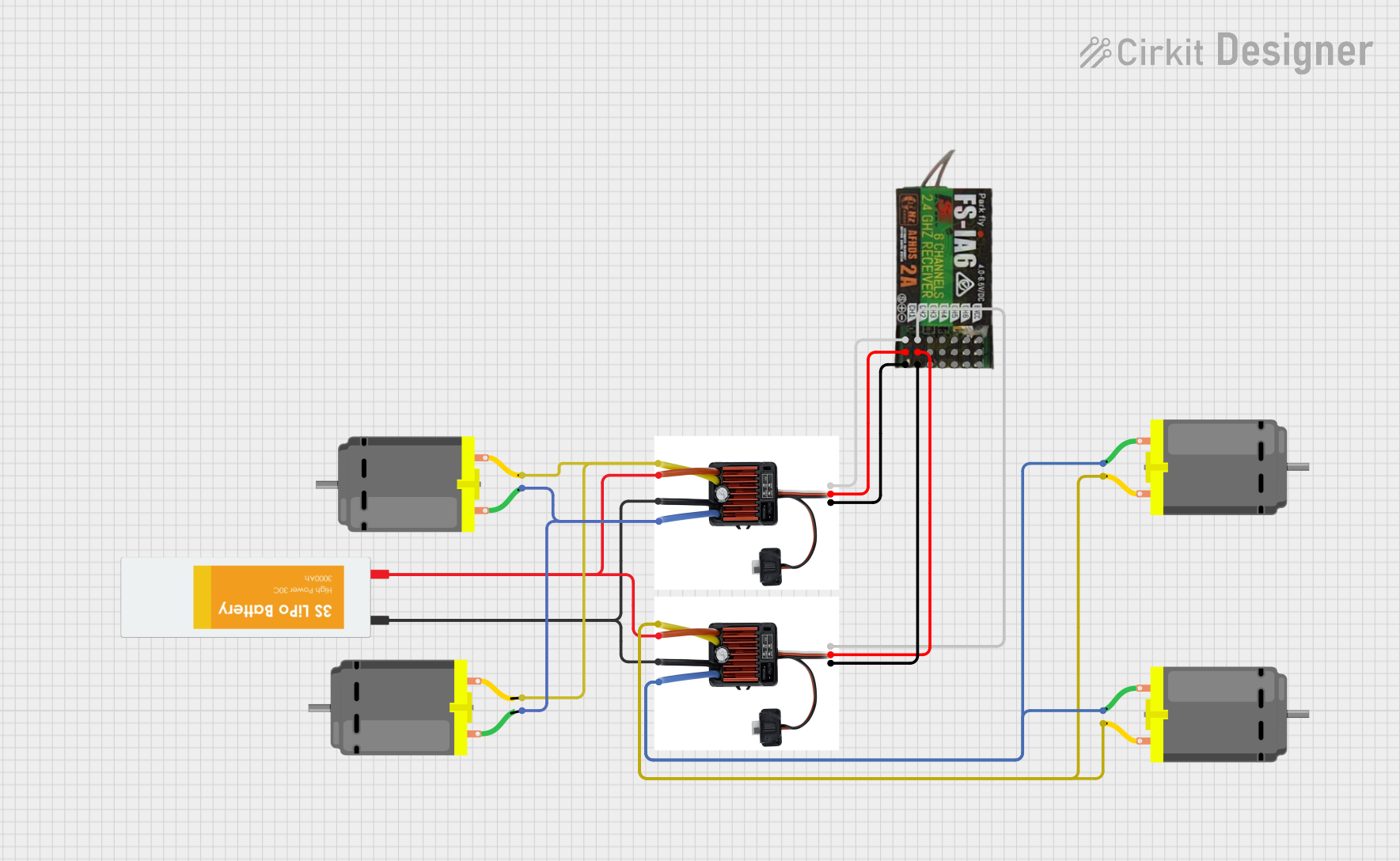 Open Project in Cirkit Designer
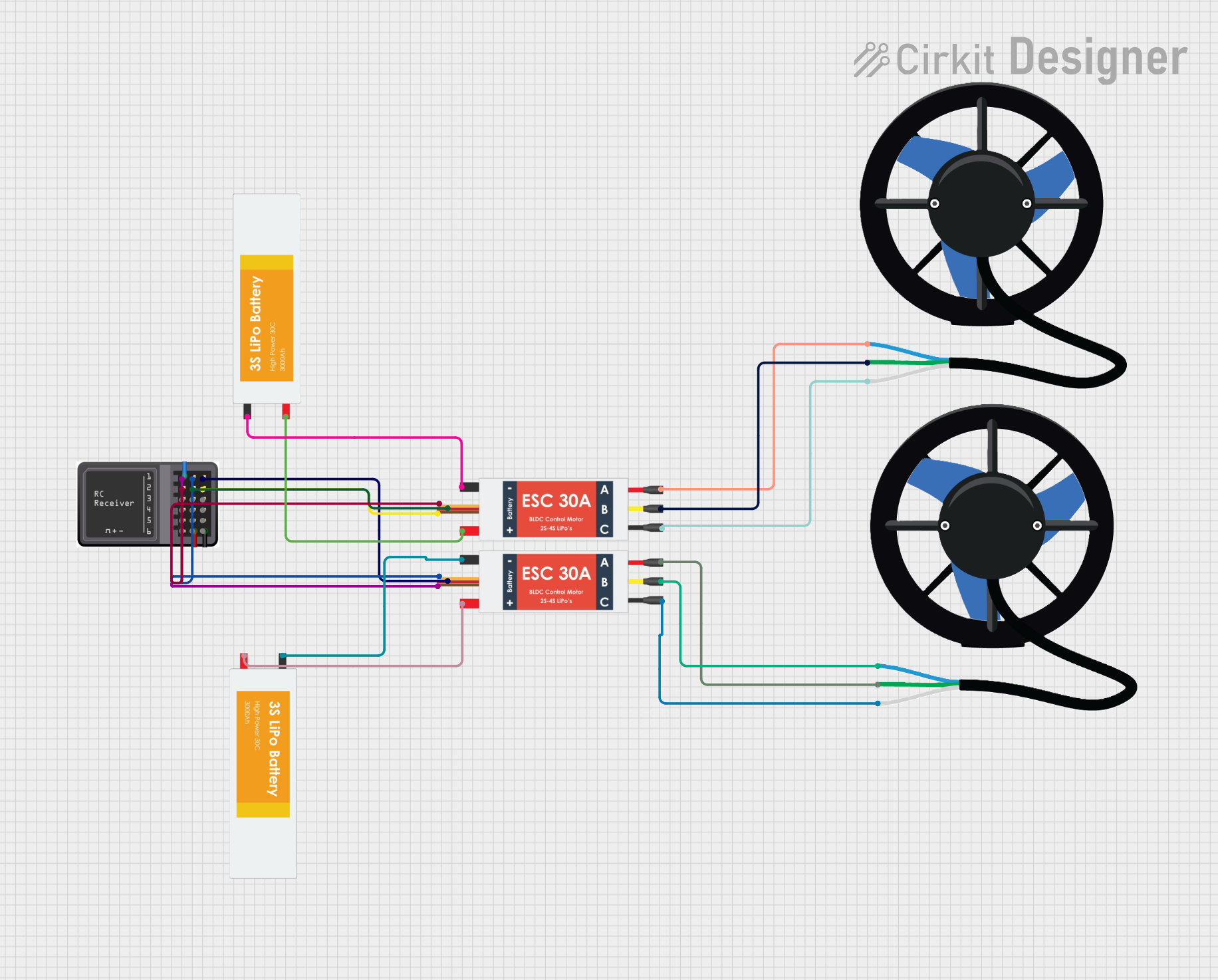 Open Project in Cirkit Designer
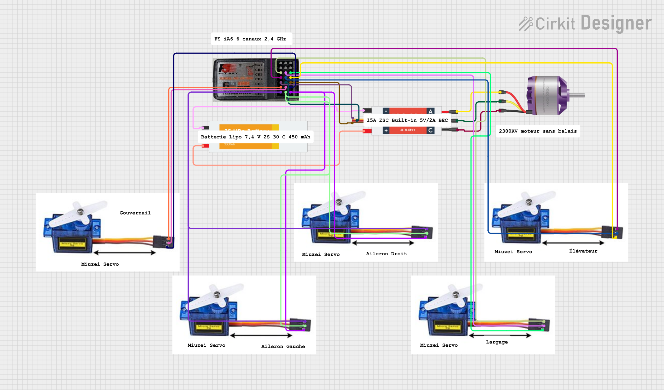 Open Project in Cirkit Designer
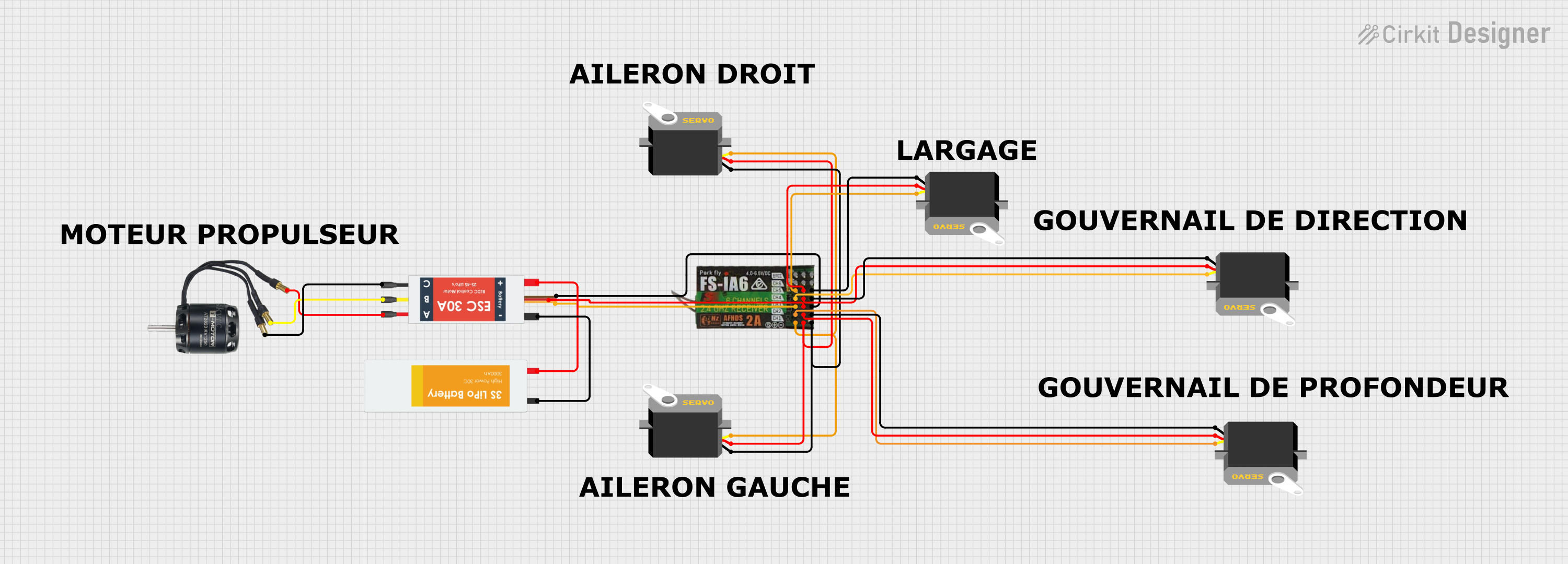 Open Project in Cirkit Designer
Explore Projects Built with EPW6 2.4GHz ELRS PWM Receiver
Open Project in Cirkit DesignerOpen Project in Cirkit DesignerOpen Project in Cirkit DesignerOpen Project in Cirkit DesignerCommon Applications and Use Cases
- RC airplanes, helicopters, and drones
- Remote-controlled cars and boats
- Robotics and automation systems
- Any project requiring long-range, low-latency wireless communication with PWM output
Technical Specifications
Below are the key technical details of the EPW6 receiver:
| Parameter | Specification |
|---|---|
| Operating Frequency | 2.4GHz |
| Protocol | ExpressLRS (ELRS) |
| Input Voltage Range | 5V - 10V |
| PWM Output Channels | 6 channels |
| Latency | As low as 3ms (depending on ELRS settings) |
| Antenna Type | Integrated or external (depending on model) |
| Dimensions | 20mm x 15mm x 5mm |
| Weight | 2 grams |
| Binding Method | ELRS binding phrase or manual bind button |
| Firmware Compatibility | ExpressLRS firmware (upgradable) |
Pin Configuration and Descriptions
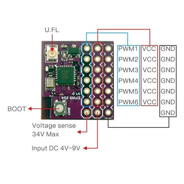
The EPW6 receiver has a simple pin layout for easy integration into your projects. Below is the pin configuration:
| Pin | Label | Description |
|---|---|---|
| 1 | VCC | Power input (5V - 10V) |
| 2 | GND | Ground connection |
| 3 | CH1 | PWM output for Channel 1 |
| 4 | CH2 | PWM output for Channel 2 |
| 5 | CH3 | PWM output for Channel 3 |
| 6 | CH4 | PWM output for Channel 4 |
| 7 | CH5 | PWM output for Channel 5 |
| 8 | CH6 | PWM output for Channel 6 |
| 9 | BIND | Bind button for pairing with transmitter |
Usage Instructions
How to Use the EPW6 in a Circuit
- Powering the Receiver: Connect the VCC pin to a 5V-10V power source and the GND pin to ground.
- Connecting PWM Outputs: Connect the desired CH1-CH6 pins to the PWM input pins of your servos, ESCs, or other devices.
- Binding the Receiver:
- If using an ELRS transmitter with a binding phrase, the receiver will automatically bind when powered on.
- For manual binding, press and hold the BIND button while powering on the receiver. Follow the transmitter's binding procedure.
- Configuring ELRS Settings: Use the ExpressLRS Configurator to update firmware or adjust settings such as packet rate and telemetry.
Important Considerations and Best Practices
- Ensure the receiver's antenna is positioned away from metal components to avoid signal interference.
- Use a stable power supply within the specified voltage range to prevent damage.
- Update the receiver's firmware to the latest version for optimal performance and compatibility.
- When using multiple PWM channels, ensure the connected devices do not exceed the receiver's current handling capacity.
Example: Using EPW6 with Arduino UNO
The EPW6 can be connected to an Arduino UNO to read PWM signals. Below is an example code snippet:
// Example code to read PWM signals from EPW6 receiver using Arduino UNO
// Connect CH1 of EPW6 to pin 2 of Arduino UNO

const int pwmPin = 2; // Pin connected to CH1 of EPW6
unsigned long pulseWidth; // Variable to store pulse width

void setup() {
  pinMode(pwmPin, INPUT); // Set the pin as input
  Serial.begin(9600); // Initialize serial communication
}

void loop() {
  // Measure the duration of the HIGH state of the PWM signal
  pulseWidth = pulseIn(pwmPin, HIGH);

  // Print the pulse width in microseconds
  Serial.print("Pulse Width: ");
  Serial.print(pulseWidth);
  Serial.println(" us");

  delay(100); // Delay for readability
}
Notes:
- Ensure the Arduino is powered properly and shares a common ground with the EPW6 receiver.
- The
pulseIn()function measures the duration of the PWM signal's HIGH state, which corresponds to the servo position or control signal.
Troubleshooting and FAQs
Common Issues and Solutions
Receiver Not Binding to Transmitter:
- Ensure the transmitter and receiver are using the same ELRS firmware version.
- Verify that the binding phrase matches or follow the manual binding procedure.
- Check the power supply to the receiver.
No PWM Output:
- Confirm that the receiver is properly bound to the transmitter.
- Check the connections between the receiver and the connected devices.
- Ensure the transmitter is configured to output signals on the correct channels.
Intermittent Signal Loss:
- Ensure the antenna is properly positioned and not obstructed.
- Reduce interference by keeping the receiver away from high-power electronics.
Firmware Update Fails:
- Use the correct firmware file for the EPW6 receiver.
- Ensure a stable USB connection when flashing firmware via the ExpressLRS Configurator.
FAQs
Q: Can the EPW6 receiver be used with other protocols besides ELRS?
A: No, the EPW6 is specifically designed for the ExpressLRS protocol and is not compatible with other protocols.
Q: What is the maximum range of the EPW6 receiver?
A: The range depends on the ELRS settings and environment but can exceed 10km in optimal conditions.
Q: How many devices can be controlled simultaneously using the EPW6?
A: The EPW6 supports up to 6 PWM channels, allowing control of up to 6 devices.
Q: Is telemetry supported on the EPW6?
A: Yes, the EPW6 supports telemetry when configured with compatible ELRS transmitters.
By following this documentation, users can effectively integrate the EPW6 2.4GHz ELRS PWM Receiver into their projects for reliable and efficient remote control functionality.