How to Use Motor Driver 2: Examples, Pinouts, and Specs
Introduction
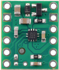
The Motor Driver 2 is an integrated circuit designed to control the direction and speed of DC motors or stepper motors. It acts as an interface between low-power control signals (e.g., from a microcontroller) and the high-power requirements of motors. By providing the necessary current and voltage levels, the Motor Driver 2 ensures efficient motor operation while protecting the control circuitry.
Explore Projects Built with Motor Driver 2
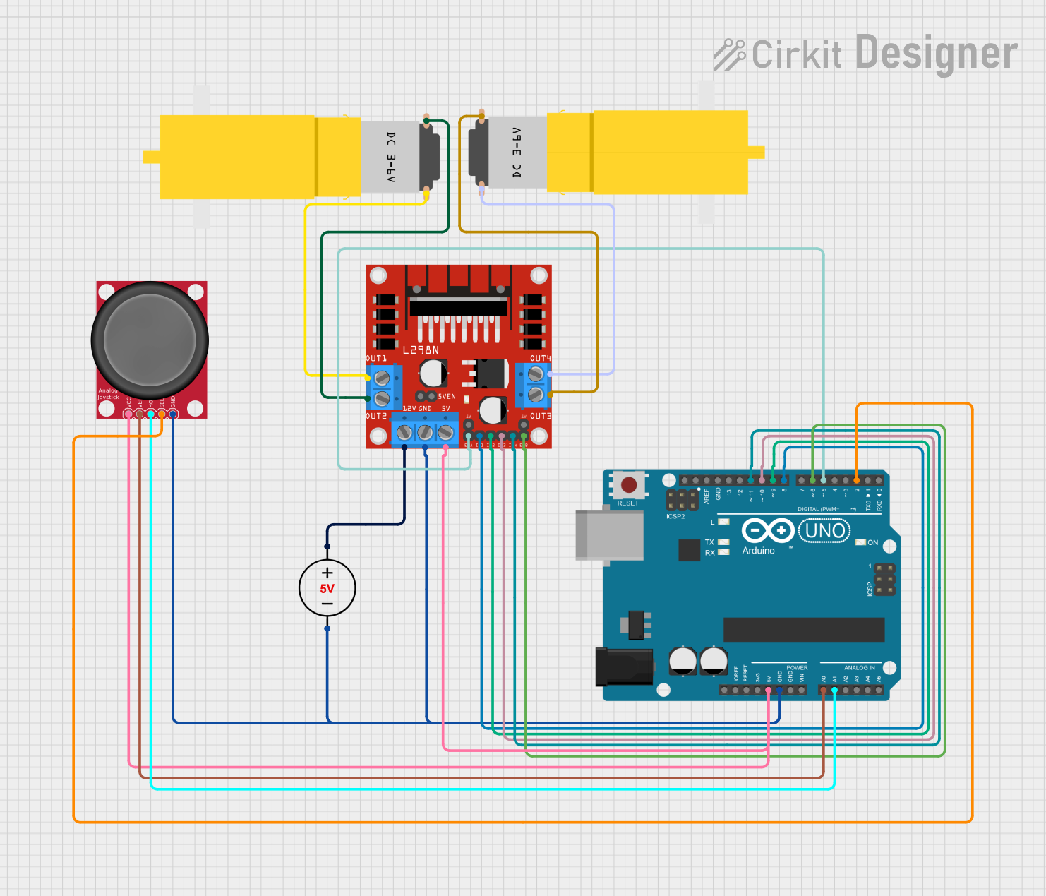


Explore Projects Built with Motor Driver 2
Common Applications and Use Cases
- Robotics: Driving wheels or robotic arms
- Industrial automation: Controlling conveyor belts or actuators
- Smart home devices: Operating fans, blinds, or small appliances
- Educational projects: Motorized systems for learning and prototyping
Technical Specifications
Key Technical Details
- Operating Voltage: 4.5V to 36V
- Output Current: Up to 2A per channel
- Number of Channels: 2 (can control two motors independently)
- Logic Voltage: 3.3V or 5V compatible
- Control Inputs: PWM (Pulse Width Modulation) for speed control
- Protection Features: Thermal shutdown, overcurrent protection, and undervoltage lockout
- Package Type: DIP or surface-mount (varies by manufacturer)
Pin Configuration and Descriptions
The Motor Driver 2 typically has the following pin configuration:
| Pin Number | Pin Name | Description |
|---|---|---|
| 1 | IN1 | Input signal for controlling Motor 1 direction |
| 2 | IN2 | Input signal for controlling Motor 1 direction |
| 3 | ENA | Enable pin for Motor 1 (PWM input for speed control) |
| 4 | OUT1 | Output pin connected to one terminal of Motor 1 |
| 5 | OUT2 | Output pin connected to the other terminal of Motor 1 |
| 6 | GND | Ground connection |
| 7 | VCC | Logic voltage supply (3.3V or 5V) |
| 8 | VM | Motor power supply (4.5V to 36V) |
| 9 | OUT3 | Output pin connected to one terminal of Motor 2 |
| 10 | OUT4 | Output pin connected to the other terminal of Motor 2 |
| 11 | ENB | Enable pin for Motor 2 (PWM input for speed control) |
| 12 | IN3 | Input signal for controlling Motor 2 direction |
| 13 | IN4 | Input signal for controlling Motor 2 direction |
Usage Instructions
How to Use the Component in a Circuit
Power Connections:
- Connect the VM pin to the motor power supply (ensure it matches the motor's voltage rating).
- Connect the VCC pin to the logic voltage supply (3.3V or 5V, depending on your microcontroller).
- Connect the GND pin to the ground of both the motor power supply and the microcontroller.
Motor Connections:
- Connect the motor terminals to the OUT1 and OUT2 pins for Motor 1, and OUT3 and OUT4 pins for Motor 2.
Control Signals:
- Use the IN1 and IN2 pins to control the direction of Motor 1, and IN3 and IN4 for Motor 2.
- Apply a PWM signal to the ENA pin for Motor 1 and the ENB pin for Motor 2 to control their speeds.
Direction Control:
- Set IN1 = HIGH and IN2 = LOW to rotate Motor 1 in one direction.
- Set IN1 = LOW and IN2 = HIGH to rotate Motor 1 in the opposite direction.
- Similarly, use IN3 and IN4 for Motor 2.
Important Considerations and Best Practices
- Ensure the motor power supply voltage matches the motor's specifications to avoid damage.
- Use appropriate heat sinks or cooling mechanisms if operating at high currents for extended periods.
- Avoid exceeding the maximum current rating (2A per channel) to prevent damage to the IC.
- Use decoupling capacitors near the VM and VCC pins to reduce noise and voltage spikes.
Example Code for Arduino UNO
Below is an example of how to control a DC motor using the Motor Driver 2 and an Arduino UNO:
// Define motor control pins
const int IN1 = 2;  // Motor 1 direction control pin
const int IN2 = 3;  // Motor 1 direction control pin
const int ENA = 9;  // Motor 1 speed control (PWM pin)

void setup() {
  // Set motor control pins as outputs
  pinMode(IN1, OUTPUT);
  pinMode(IN2, OUTPUT);
  pinMode(ENA, OUTPUT);
}

void loop() {
  // Rotate motor in one direction at 50% speed
  digitalWrite(IN1, HIGH);  // Set IN1 HIGH
  digitalWrite(IN2, LOW);   // Set IN2 LOW
  analogWrite(ENA, 128);    // Set PWM duty cycle to 50% (128/255)

  delay(2000);  // Run motor for 2 seconds

  // Rotate motor in the opposite direction at full speed
  digitalWrite(IN1, LOW);   // Set IN1 LOW
  digitalWrite(IN2, HIGH);  // Set IN2 HIGH
  analogWrite(ENA, 255);    // Set PWM duty cycle to 100% (255/255)

  delay(2000);  // Run motor for 2 seconds

  // Stop the motor
  digitalWrite(IN1, LOW);   // Set IN1 LOW
  digitalWrite(IN2, LOW);   // Set IN2 LOW
  analogWrite(ENA, 0);      // Set PWM duty cycle to 0% (motor off)

  delay(2000);  // Wait for 2 seconds before repeating
}
Troubleshooting and FAQs
Common Issues and Solutions
Motor Does Not Spin:
- Check the power supply connections to VM and VCC.
- Verify that the enable pin (e.g., ENA) is receiving a valid PWM signal.
- Ensure the motor connections to OUT1, OUT2, OUT3, and OUT4 are secure.
Motor Spins in the Wrong Direction:
- Reverse the logic levels on the direction control pins (e.g., IN1 and IN2).
Motor Driver Overheats:
- Ensure the current drawn by the motor does not exceed 2A per channel.
- Add a heat sink or improve ventilation around the IC.
PWM Control Not Working:
- Verify that the PWM signal is being generated correctly by the microcontroller.
- Check the duty cycle of the PWM signal to ensure it matches the desired speed.
FAQs
Can I use the Motor Driver 2 with a stepper motor? Yes, the Motor Driver 2 can control stepper motors by coordinating the inputs to the two channels. Refer to stepper motor control guides for details.
What happens if I exceed the maximum current rating? The IC may overheat or trigger its overcurrent protection. Prolonged overcurrent conditions can permanently damage the IC.
Can I use a 12V motor with a 5V logic supply? Yes, as long as the motor power supply (VM) is 12V and the logic supply (VCC) is 5V, the Motor Driver 2 will operate correctly.