Cirkit Designer Logo
Cirkit Designer
Your all-in-one circuit design IDE
Home / 
Component Documentation

How to Use 4xAA_bare: Examples, Pinouts, and Specs

Image of 4xAA_bare
Cirkit Designer LogoDesign with 4xAA_bare in Cirkit Designer

Introduction

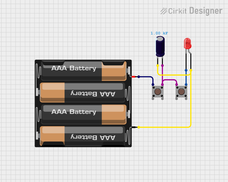
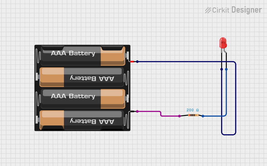
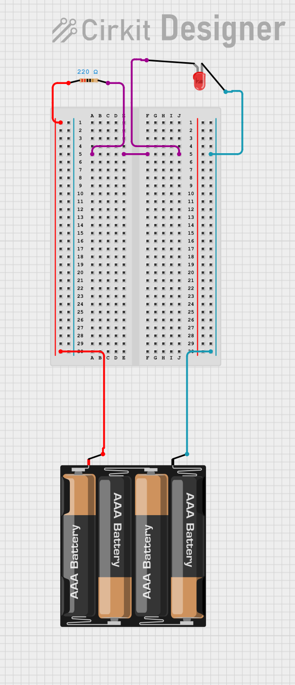
The 4xAA_bare is a battery holder designed to securely house four AA batteries in series. This configuration provides a compact and portable power source for a wide range of electronic projects. When fully loaded with standard 1.5V AA batteries, the holder delivers a total output voltage of approximately 6V. It is commonly used in DIY electronics, robotics, portable devices, and low-power embedded systems.

Explore Projects Built with 4xAA_bare

Use Cirkit Designer to design, explore, and prototype these projects online. Some projects support real-time simulation. Click "Open Project" to start designing instantly!
Battery-Powered LED Circuit with Pushbutton Control and Capacitance Smoothing
Image of Coding and Robotics activity 3: A project utilizing 4xAA_bare in a practical application
This circuit consists of a 4 x AAA battery mount providing power, two pushbuttons acting as switches, an electrolytic capacitor for smoothing voltage fluctuations, and a red LED as an indicator. The LED lights up when either pushbutton is pressed, with the capacitor likely serving to debounce the pushbutton signal or provide a more stable LED operation. There is no microcontroller in this circuit, indicating a simple, direct-control user interface.
Cirkit Designer LogoOpen Project in Cirkit Designer
Simple Battery-Powered LED Circuit
Image of Coding Assignment 2: A project utilizing 4xAA_bare in a practical application
This is a basic LED circuit with a series resistor for current limiting. It is powered by a 4 x AAA battery mount, with the resistor ensuring that the LED operates within safe current levels to prevent damage.
Cirkit Designer LogoOpen Project in Cirkit Designer
Battery-Powered LED Circuit with Resistor
Image of Project 1: Glowing LED: A project utilizing 4xAA_bare in a practical application
This circuit consists of a 4 x AAA battery mount powering a red LED through a 220-ohm resistor. The resistor limits the current flowing through the LED, which is connected in series with the battery pack to ensure safe operation and prevent damage to the LED.
Cirkit Designer LogoOpen Project in Cirkit Designer
Arduino Nano and NRF24L01 Based Wireless Remote Control
Image of P.T.S CAR , REMOTE , ADVANCE , FINAL V1: A project utilizing 4xAA_bare in a practical application
This circuit features an Arduino Nano microcontroller interfaced with an NRF24L01 wireless transceiver module, powered by a 4 x AAA battery mount. Four pushbuttons are connected to the Arduino's digital inputs with pull-up resistors, and they are used to send different wireless commands via the NRF24L01 module when pressed. The Arduino's SPI interface (D11/MOSI, D12/MISO, D13/SCK) is used for communication with the NRF24L01, and digital pins D9 and D10 are used for the module's CE and CSN pins, respectively.
Cirkit Designer LogoOpen Project in Cirkit Designer

Explore Projects Built with 4xAA_bare

Use Cirkit Designer to design, explore, and prototype these projects online. Some projects support real-time simulation. Click "Open Project" to start designing instantly!
Image of Coding and Robotics activity 3: A project utilizing 4xAA_bare in a practical application
Battery-Powered LED Circuit with Pushbutton Control and Capacitance Smoothing
This circuit consists of a 4 x AAA battery mount providing power, two pushbuttons acting as switches, an electrolytic capacitor for smoothing voltage fluctuations, and a red LED as an indicator. The LED lights up when either pushbutton is pressed, with the capacitor likely serving to debounce the pushbutton signal or provide a more stable LED operation. There is no microcontroller in this circuit, indicating a simple, direct-control user interface.
Cirkit Designer LogoOpen Project in Cirkit Designer
Image of Coding Assignment 2: A project utilizing 4xAA_bare in a practical application
Simple Battery-Powered LED Circuit
This is a basic LED circuit with a series resistor for current limiting. It is powered by a 4 x AAA battery mount, with the resistor ensuring that the LED operates within safe current levels to prevent damage.
Cirkit Designer LogoOpen Project in Cirkit Designer
Image of Project 1: Glowing LED: A project utilizing 4xAA_bare in a practical application
Battery-Powered LED Circuit with Resistor
This circuit consists of a 4 x AAA battery mount powering a red LED through a 220-ohm resistor. The resistor limits the current flowing through the LED, which is connected in series with the battery pack to ensure safe operation and prevent damage to the LED.
Cirkit Designer LogoOpen Project in Cirkit Designer
Image of P.T.S CAR , REMOTE , ADVANCE , FINAL V1: A project utilizing 4xAA_bare in a practical application
Arduino Nano and NRF24L01 Based Wireless Remote Control
This circuit features an Arduino Nano microcontroller interfaced with an NRF24L01 wireless transceiver module, powered by a 4 x AAA battery mount. Four pushbuttons are connected to the Arduino's digital inputs with pull-up resistors, and they are used to send different wireless commands via the NRF24L01 module when pressed. The Arduino's SPI interface (D11/MOSI, D12/MISO, D13/SCK) is used for communication with the NRF24L01, and digital pins D9 and D10 are used for the module's CE and CSN pins, respectively.
Cirkit Designer LogoOpen Project in Cirkit Designer

Common Applications

  • Powering small electronic circuits and microcontrollers
  • Portable robotics and motorized projects
  • Backup power for low-power devices
  • Educational and prototyping purposes

Technical Specifications

The 4xAA_bare battery holder is a simple yet essential component for powering electronic devices. Below are its key technical details:

General Specifications

Parameter Value
Battery Type AA (1.5V each)
Number of Batteries 4
Output Voltage (Nominal) 6V (1.5V x 4 in series)
Output Voltage (Rechargeable Batteries) ~4.8V (1.2V x 4 in series)
Maximum Current Dependent on battery type
Material Plastic body with metal contacts
Dimensions ~60mm x 30mm x 15mm
Weight (Empty) ~20g

Pin Configuration and Descriptions

The 4xAA_bare holder typically has two output wires for connecting to a circuit. These wires are color-coded for easy identification.

Wire Color Description
Red Positive terminal (+)
Black Negative terminal (-)

Usage Instructions

How to Use the 4xAA_bare in a Circuit

  1. Insert Batteries: Place four AA batteries into the holder, ensuring correct polarity as indicated on the holder.
  2. Connect to Circuit: Use the red wire for the positive connection and the black wire for the negative connection. Ensure proper polarity to avoid damage to your circuit.
  3. Secure Connections: Use soldering, connectors, or a breadboard to securely attach the wires to your circuit.
  4. Power Your Device: Once connected, the holder will supply power to your circuit.

Important Considerations and Best Practices

  • Battery Type: Use high-quality alkaline or rechargeable NiMH batteries for optimal performance.
  • Voltage Compatibility: Ensure your circuit can handle the nominal 6V output. If using rechargeable batteries, the output will be lower (~4.8V).
  • Current Draw: Check the current requirements of your circuit and ensure the batteries can supply sufficient current.
  • Polarity: Double-check the polarity of the connections to avoid damaging your components.
  • Heat Management: Avoid short circuits, as they can cause the batteries to overheat and potentially leak or explode.

Example: Connecting to an Arduino UNO

The 4xAA_bare can be used to power an Arduino UNO via its VIN pin. Below is an example setup:

  1. Connect the red wire (positive) to the VIN pin on the Arduino UNO.
  2. Connect the black wire (negative) to the GND pin on the Arduino UNO.
  3. Ensure the total voltage from the battery holder is within the Arduino's acceptable input range (6-12V).

Sample Code for Testing

// This code blinks an LED connected to pin 13 of the Arduino UNO.
// Ensure the Arduino is powered using the 4xAA_bare battery holder.

void setup() {
  pinMode(13, OUTPUT); // Set pin 13 as an output pin
}

void loop() {
  digitalWrite(13, HIGH); // Turn the LED on
  delay(1000);            // Wait for 1 second
  digitalWrite(13, LOW);  // Turn the LED off
  delay(1000);            // Wait for 1 second
}

Troubleshooting and FAQs

Common Issues

  1. No Power Output

    • Cause: Batteries are inserted incorrectly or are depleted.
    • Solution: Check the polarity of the batteries and replace them if necessary.
  2. Circuit Not Working

    • Cause: Incorrect wiring or loose connections.
    • Solution: Verify the connections and ensure the wires are securely attached.
  3. Overheating Batteries

    • Cause: Short circuit or excessive current draw.
    • Solution: Disconnect the holder immediately and inspect the circuit for shorts or high-current components.
  4. Voltage Too Low

    • Cause: Using rechargeable batteries or partially depleted batteries.
    • Solution: Use fresh alkaline batteries for a full 6V output.

FAQs

Q: Can I use fewer than four batteries in the holder?
A: No, the 4xAA_bare is designed to operate with four batteries in series. Using fewer batteries will result in an incomplete circuit.

Q: Is the holder waterproof?
A: No, the 4xAA_bare is not waterproof. Avoid exposing it to moisture or water.

Q: Can I use lithium AA batteries?
A: Yes, lithium AA batteries can be used, but ensure your circuit can handle the slightly higher voltage (1.7V per cell, ~6.8V total).

Q: How do I secure the holder in my project?
A: The holder can be secured using screws, adhesive, or zip ties, depending on your project requirements.