Cirkit Designer
Your all-in-one circuit design IDE
Home /
Component Documentation
How to Use bno055: Examples, Pinouts, and Specs
Introduction
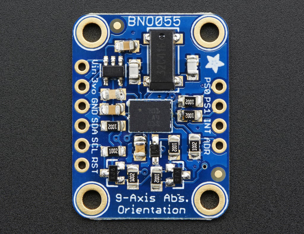
The BNO055 is a sophisticated 9-axis absolute orientation sensor developed by Adafruit. It integrates an accelerometer, gyroscope, and magnetometer to provide accurate orientation data. This sensor is ideal for applications requiring precise motion tracking and orientation detection, such as robotics, drones, virtual reality systems, and wearable devices.
Explore Projects Built with bno055
Arduino Nano and BNO055 Sensor with Bluetooth Connectivity
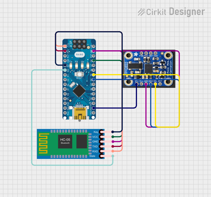
This circuit features an Arduino Nano interfaced with a BNO055 sensor and an HC-05 Bluetooth module. The Arduino communicates with the BNO055 via I2C (using A4 for SDA and A5 for SCL) and with the HC-05 via serial communication (using D0/RX and D1/TX for data transfer). The HC-05's Key and State pins are connected to D2 and D3 of the Arduino for module control, and all components share a common ground with the Arduino powered at 5V and the BNO055 at 3.3V from the Arduino's 3V3 output.
ESP32-Based Orientation Sensor Interface
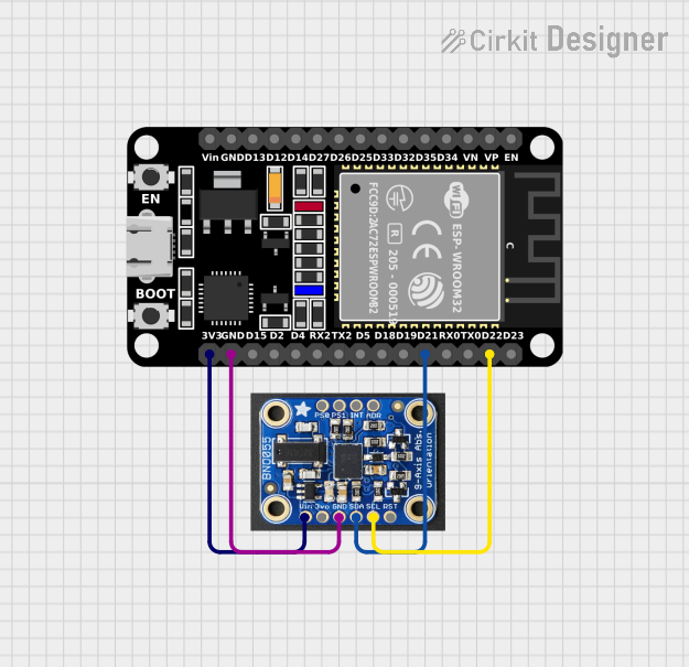
This circuit connects an ESP32 microcontroller to a BNO055 sensor. The ESP32's I2C pins (D21 for SDA and D22 for SCL) are interfaced with the BNO055's SDA and SCL pins, enabling communication between the microcontroller and the sensor. Power and ground connections are also established from the ESP32 to the BNO055, with the ESP32's 3V3 pin supplying power to the BNO055's Vin pin.
Battery-Powered Arduino UNO with BNO085 IMU and Bluetooth HC-06 for Orientation Tracking

This circuit integrates an Arduino UNO with an Adafruit BNO085 9-DOF Orientation IMU and a Bluetooth HC-06 module. The Arduino reads orientation data from the IMU via I2C and transmits it over Bluetooth, powered by a 7.4V battery.
Arduino Nano-Based Wearable Gesture Control Interface with Bluetooth Connectivity

This is a battery-powered sensor system with Bluetooth communication, featuring an Arduino Nano for control, an MPU-6050 for motion sensing, and an HC-05 module for wireless data transmission. It includes a vibration motor for haptic feedback, a flex resistor as an additional sensor, and a piezo speaker and LED for alerts or status indication.
Explore Projects Built with bno055
Arduino Nano and BNO055 Sensor with Bluetooth Connectivity
This circuit features an Arduino Nano interfaced with a BNO055 sensor and an HC-05 Bluetooth module. The Arduino communicates with the BNO055 via I2C (using A4 for SDA and A5 for SCL) and with the HC-05 via serial communication (using D0/RX and D1/TX for data transfer). The HC-05's Key and State pins are connected to D2 and D3 of the Arduino for module control, and all components share a common ground with the Arduino powered at 5V and the BNO055 at 3.3V from the Arduino's 3V3 output.
ESP32-Based Orientation Sensor Interface
This circuit connects an ESP32 microcontroller to a BNO055 sensor. The ESP32's I2C pins (D21 for SDA and D22 for SCL) are interfaced with the BNO055's SDA and SCL pins, enabling communication between the microcontroller and the sensor. Power and ground connections are also established from the ESP32 to the BNO055, with the ESP32's 3V3 pin supplying power to the BNO055's Vin pin.
Battery-Powered Arduino UNO with BNO085 IMU and Bluetooth HC-06 for Orientation Tracking
This circuit integrates an Arduino UNO with an Adafruit BNO085 9-DOF Orientation IMU and a Bluetooth HC-06 module. The Arduino reads orientation data from the IMU via I2C and transmits it over Bluetooth, powered by a 7.4V battery.
Arduino Nano-Based Wearable Gesture Control Interface with Bluetooth Connectivity
This is a battery-powered sensor system with Bluetooth communication, featuring an Arduino Nano for control, an MPU-6050 for motion sensing, and an HC-05 module for wireless data transmission. It includes a vibration motor for haptic feedback, a flex resistor as an additional sensor, and a piezo speaker and LED for alerts or status indication.
Technical Specifications
Key Technical Details
| Parameter | Value |
|---|---|
| Operating Voltage | 2.4V - 3.6V |
| Operating Current | 12 mA (typical) |
| Power Consumption | 3.4 mA (low power mode) |
| Communication | I2C, UART |
| Accelerometer Range | ±2g, ±4g, ±8g, ±16g |
| Gyroscope Range | ±125°/s, ±250°/s, ±500°/s, ±1000°/s, ±2000°/s |
| Magnetometer Range | ±1300 µT |
| Operating Temperature | -40°C to +85°C |
Pin Configuration and Descriptions
| Pin | Name | Description |
|---|---|---|
| 1 | VIN | Power supply (3.3V) |
| 2 | GND | Ground |
| 3 | SDA | I2C Data |
| 4 | SCL | I2C Clock |
| 5 | PS0 | Protocol select (I2C or UART) |
| 6 | PS1 | Protocol select (I2C or UART) |
| 7 | RST | Reset |
| 8 | INT | Interrupt |
Usage Instructions
How to Use the BNO055 in a Circuit
- Power Supply: Connect the VIN pin to a 3.3V power source and the GND pin to the ground.
- I2C Communication: Connect the SDA pin to the SDA pin on your microcontroller and the SCL pin to the SCL pin on your microcontroller.
- Protocol Selection: Set the PS0 and PS1 pins to select the I2C protocol (both should be connected to GND).
- Reset: Optionally, connect the RST pin to a digital pin on your microcontroller to reset the sensor programmatically.
- Interrupt: Optionally, connect the INT pin to a digital pin on your microcontroller to handle interrupts.
Important Considerations and Best Practices
- Power Supply: Ensure the sensor is powered with a stable 3.3V supply to avoid inaccurate readings.
- I2C Pull-up Resistors: Use appropriate pull-up resistors (typically 4.7kΩ) on the SDA and SCL lines.
- Mounting: Mount the sensor securely to avoid vibrations that can affect the readings.
- Calibration: Perform sensor calibration for accurate orientation data.
Example Code for Arduino UNO
#include <Wire.h>
#include <Adafruit_Sensor.h>
#include <Adafruit_BNO055.h>

// Create an instance of the sensor
Adafruit_BNO055 bno = Adafruit_BNO055(55);

void setup() {
  Serial.begin(9600);
  // Initialize the sensor
  if (!bno.begin()) {
    Serial.print("No BNO055 detected. Check your wiring or I2C ADDR!");
    while (1);
  }
  delay(1000);
  bno.setExtCrystalUse(true);
}

void loop() {
  // Get the orientation data
  sensors_event_t event;
  bno.getEvent(&event);

  // Print the orientation data
  Serial.print("X: ");
  Serial.print(event.orientation.x);
  Serial.print("\tY: ");
  Serial.print(event.orientation.y);
  Serial.print("\tZ: ");
  Serial.println(event.orientation.z);

  delay(1000);
}
Troubleshooting and FAQs
Common Issues
- Sensor Not Detected: Ensure the wiring is correct and the sensor is powered properly. Check the I2C address.
- Inaccurate Readings: Perform sensor calibration and ensure the sensor is mounted securely.
- Communication Errors: Verify the pull-up resistors on the I2C lines and check for loose connections.
Solutions and Tips for Troubleshooting
- Check Connections: Ensure all connections are secure and correct.
- Use a Stable Power Supply: Fluctuations in power can cause erratic behavior.
- Calibrate the Sensor: Follow the calibration procedure in the sensor's datasheet for accurate readings.
- Check I2C Address: Ensure the correct I2C address is used in the code.
By following this documentation, users can effectively integrate and utilize the BNO055 sensor in their projects, ensuring accurate and reliable orientation data.