How to Use TPS2113A: Examples, Pinouts, and Specs
Introduction
The TPS2113A is a power multiplexer manufactured by Texas Instruments (TI). It is designed to seamlessly switch between two power sources, ensuring a reliable and uninterrupted power supply to the load. This component is particularly useful in applications where redundancy or automatic power source selection is required. With its low on-resistance and fast switching times, the TPS2113A is ideal for high-efficiency systems that demand minimal voltage drop.
Explore Projects Built with TPS2113A


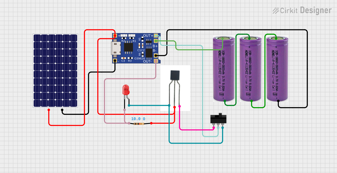

Explore Projects Built with TPS2113A
Common Applications
- Battery-powered devices with dual power sources (e.g., battery and USB power)
- Portable electronics
- Redundant power supply systems
- Industrial and automotive systems requiring power source prioritization
- Embedded systems and microcontroller-based designs
Technical Specifications
Key Technical Details
| Parameter | Value |
|---|---|
| Input Voltage Range | 2.8 V to 5.5 V |
| Output Voltage Range | 2.8 V to 5.5 V |
| Maximum Output Current | 1.25 A |
| On-Resistance (RON) | 84 mΩ (typical) |
| Switching Time | 50 µs (typical) |
| Control Logic Voltage | 0 V to 5.5 V |
| Operating Temperature Range | -40°C to 85°C |
| Package Options | 8-pin SOIC (D) and 8-pin VSSOP (DGK) |
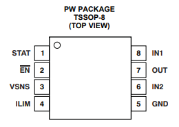
Pin Configuration and Descriptions
The TPS2113A is available in an 8-pin SOIC or VSSOP package. Below is the pinout and description:
| Pin Number | Pin Name | Type | Description |
|---|---|---|---|
| 1 | IN1 | Power Input | Primary power input source. Connect to the first power supply. |
| 2 | IN2 | Power Input | Secondary power input source. Connect to the second power supply. |
| 3 | GND | Ground | Ground reference for the device. |
| 4 | EN | Input | Enable pin. Logic high enables the device; logic low disables it. |
| 5 | CT | Capacitor | Connect a capacitor to set the switchover delay time. |
| 6 | OUT | Power Output | Output to the load. |
| 7 | SEL | Input | Select pin. Logic high selects IN2; logic low selects IN1. |
| 8 | STAT | Output | Status pin. Indicates which input is supplying power (logic high for IN2). |
Usage Instructions
How to Use the TPS2113A in a Circuit
Power Source Connections:
- Connect the primary power source to the IN1 pin.
- Connect the secondary power source to the IN2 pin.
- Ensure both power sources are within the specified input voltage range (2.8 V to 5.5 V).
Output Connection:
- Connect the load to the OUT pin. The TPS2113A will automatically switch between IN1 and IN2 based on the logic at the SEL pin.
Control Logic:
- Use the SEL pin to select the active power source:
- Logic low (0 V): IN1 is selected.
- Logic high (3.3 V or 5 V): IN2 is selected.
- The EN pin can be used to enable or disable the device:
- Logic high (3.3 V or 5 V): Device is enabled.
- Logic low (0 V): Device is disabled.
- Use the SEL pin to select the active power source:
Capacitor Selection:
- Connect a capacitor to the CT pin to set the switchover delay time. A typical value is 1 µF for a delay of approximately 50 ms.
Status Monitoring:
- Use the STAT pin to monitor the active power source. A logic high indicates that IN2 is supplying power, while a logic low indicates IN1 is active.
Important Considerations
- Ensure that the input power sources are stable and within the specified voltage range.
- Use decoupling capacitors (e.g., 0.1 µF and 10 µF) on the input and output pins to reduce noise and improve stability.
- Avoid exceeding the maximum output current of 1.25 A to prevent damage to the device.
- Place the TPS2113A as close as possible to the power sources and load to minimize voltage drops and noise.
Example: Using TPS2113A with an Arduino UNO
The following example demonstrates how to use the TPS2113A to switch between USB power and a battery for an Arduino UNO:
Circuit Connections
- Connect the USB 5 V supply to IN1.
- Connect the battery (e.g., 3.7 V Li-ion) to IN2.
- Connect the OUT pin to the Arduino's 5 V pin.
- Use a GPIO pin from the Arduino to control the SEL pin.
Arduino Code
// Define the SEL pin connected to the Arduino
const int selPin = 7; // GPIO pin 7 controls the power source selection

void setup() {
  pinMode(selPin, OUTPUT); // Set SEL pin as an output
  digitalWrite(selPin, LOW); // Start with IN1 (USB power) as the active source
}

void loop() {
  // Example: Switch to IN2 (battery power) after 10 seconds
  delay(10000); // Wait for 10 seconds
  digitalWrite(selPin, HIGH); // Switch to IN2 (battery power)

  // Example: Switch back to IN1 (USB power) after another 10 seconds
  delay(10000); // Wait for 10 seconds
  digitalWrite(selPin, LOW); // Switch back to IN1 (USB power)
}
Troubleshooting and FAQs
Common Issues and Solutions
No Output Voltage:
- Ensure the EN pin is set to logic high to enable the device.
- Verify that at least one power source is connected and within the specified voltage range.
Frequent Switching Between Inputs:
- Check the stability of the input power sources. Unstable or noisy inputs can cause the device to switch frequently.
- Increase the capacitor value on the CT pin to add more delay to the switchover time.
Excessive Voltage Drop:
- Ensure the load current does not exceed the maximum output current of 1.25 A.
- Use low-resistance connections and minimize the distance between the TPS2113A and the load.
STAT Pin Not Responding:
- Verify the logic levels at the SEL pin. The STAT pin reflects the active input source based on the SEL pin state.
FAQs
Q1: Can the TPS2113A handle higher voltages than 5.5 V?
No, the maximum input voltage for the TPS2113A is 5.5 V. Exceeding this limit may damage the device.
Q2: What happens if both power sources are unavailable?
If neither IN1 nor IN2 is within the valid voltage range, the output will be disabled, and no power will be supplied to the load.
Q3: Can I use the TPS2113A for 3.3 V systems?
Yes, the TPS2113A supports input and output voltages as low as 2.8 V, making it suitable for 3.3 V systems.
Q4: How do I prioritize one power source over the other?
Use the SEL pin to select the preferred power source. For example, set SEL to logic low to prioritize IN1 or logic high to prioritize IN2.
This concludes the documentation for the TPS2113A power multiplexer. For more details, refer to the official datasheet provided by Texas Instruments at TI.com.