
How to Use MM8108-MF15457: Examples, Pinouts, and Specs
 Design with MM8108-MF15457 in Cirkit Designer
Introduction
The MM8108-MF15457, manufactured by Morse Micro, is a low-power, high-accuracy real-time clock (RTC) integrated circuit. It is designed to provide precise timekeeping functions for a wide range of electronic applications. This component is ideal for systems requiring accurate time and date tracking, even during power interruptions, thanks to its built-in oscillator and battery backup capability.
Explore Projects Built with MM8108-MF15457
 Open Project in Cirkit Designer
 Open Project in Cirkit Designer
 Open Project in Cirkit Designer
 Open Project in Cirkit Designer
Explore Projects Built with MM8108-MF15457
Open Project in Cirkit DesignerOpen Project in Cirkit DesignerOpen Project in Cirkit DesignerOpen Project in Cirkit DesignerCommon Applications and Use Cases
- Timekeeping in microcontroller-based systems
- Data logging applications
- Smart home devices
- Industrial automation systems
- Wearable electronics
- IoT devices requiring low-power operation
Technical Specifications
The MM8108-MF15457 is engineered for reliability and efficiency. Below are its key technical specifications:
| Parameter | Value |
|---|---|
| Operating Voltage Range | 1.8V to 5.5V |
| Current Consumption | 0.5 µA (typical, at 3.0V) |
| Timekeeping Accuracy | ±3 ppm at 25°C |
| Oscillator Frequency | 32.768 kHz |
| Backup Battery Voltage | 1.2V to 3.6V |
| Communication Interface | I²C (up to 400 kHz) |
| Operating Temperature Range | -40°C to +85°C |
| Package Type | 8-pin SOIC |
Pin Configuration and Descriptions
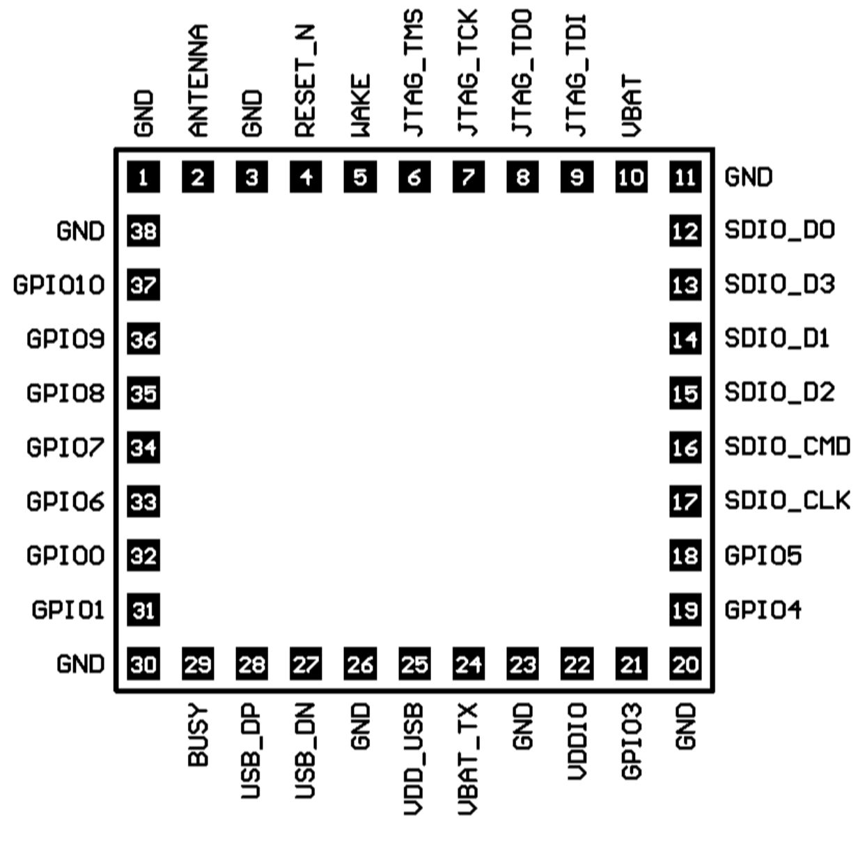
The MM8108-MF15457 features an 8-pin configuration. Below is the pinout and description:
| Pin Number | Pin Name | Description |
|---|---|---|
| 1 | VCC | Main power supply input (1.8V to 5.5V) |
| 2 | GND | Ground connection |
| 3 | SDA | I²C data line |
| 4 | SCL | I²C clock line |
| 5 | VBAT | Backup battery input (1.2V to 3.6V) |
| 6 | INT | Interrupt output for alarms or events |
| 7 | CLKOUT | Clock output for external devices |
| 8 | NC | No connection (leave unconnected) |
Usage Instructions
The MM8108-MF15457 is straightforward to integrate into a circuit. Below are the steps and best practices for using this RTC:
Circuit Integration
- Power Supply: Connect the VCC pin to the main power supply (1.8V to 5.5V) and the GND pin to the ground.
- Backup Battery: Connect a backup battery (1.2V to 3.6V) to the VBAT pin to ensure uninterrupted timekeeping during power outages.
- I²C Communication: Connect the SDA and SCL pins to the corresponding I²C lines of your microcontroller. Use pull-up resistors (typically 4.7 kΩ) on both lines.
- Interrupts and Clock Output: If needed, connect the INT pin to a microcontroller GPIO pin to handle alarms or events. The CLKOUT pin can be used to provide a clock signal to other devices.
Important Considerations
- Use a decoupling capacitor (e.g., 0.1 µF) close to the VCC pin to reduce noise.
- Ensure the backup battery voltage is within the specified range to avoid damage.
- Keep the I²C lines as short as possible to minimize signal degradation.
- Configure the I²C address of the RTC in your microcontroller code (default address: 0x68).
Example Code for Arduino UNO
Below is an example of how to interface the MM8108-MF15457 with an Arduino UNO using the Wire library:
#include <Wire.h>

#define RTC_I2C_ADDRESS 0x68  // Default I²C address for MM8108-MF15457

void setup() {
  Wire.begin();  // Initialize I²C communication
  Serial.begin(9600);  // Start serial communication for debugging

  // Set the time on the RTC (e.g., 12:00:00 on 1st January 2023)
  Wire.beginTransmission(RTC_I2C_ADDRESS);
  Wire.write(0x00);  // Set pointer to seconds register
  Wire.write(0x00);  // Seconds (00)
  Wire.write(0x00);  // Minutes (00)
  Wire.write(0x12);  // Hours (12 in 24-hour format)
  Wire.write(0x01);  // Day of the week (Monday = 1)
  Wire.write(0x01);  // Date (1st)
  Wire.write(0x01);  // Month (January)
  Wire.write(0x23);  // Year (2023)
  Wire.endTransmission();

  Serial.println("RTC initialized with current time.");
}

void loop() {
  // Read the current time from the RTC
  Wire.beginTransmission(RTC_I2C_ADDRESS);
  Wire.write(0x00);  // Set pointer to seconds register
  Wire.endTransmission();

  Wire.requestFrom(RTC_I2C_ADDRESS, 7);  // Request 7 bytes (time and date)
  int seconds = Wire.read();
  int minutes = Wire.read();
  int hours = Wire.read();
  int day = Wire.read();
  int date = Wire.read();
  int month = Wire.read();
  int year = Wire.read();

  // Print the time and date to the Serial Monitor
  Serial.print("Time: ");
  Serial.print(hours, DEC);
  Serial.print(":");
  Serial.print(minutes, DEC);
  Serial.print(":");
  Serial.println(seconds, DEC);

  Serial.print("Date: ");
  Serial.print(date, DEC);
  Serial.print("/");
  Serial.print(month, DEC);
  Serial.print("/");
  Serial.println(year, DEC);

  delay(1000);  // Wait for 1 second before reading again
}
Troubleshooting and FAQs
Common Issues
RTC Not Responding on I²C Bus
- Cause: Incorrect wiring or missing pull-up resistors on SDA and SCL lines.
- Solution: Verify the connections and ensure pull-up resistors (4.7 kΩ) are present.
Incorrect Timekeeping
- Cause: Oscillator not functioning properly or incorrect initialization.
- Solution: Check the oscillator circuit and ensure the RTC is initialized correctly in the code.
Backup Battery Not Working
- Cause: Battery voltage is outside the specified range or poor connection.
- Solution: Replace the battery with one within the 1.2V to 3.6V range and check the connections.
FAQs
Q: Can the MM8108-MF15457 operate without a backup battery?
A: Yes, but timekeeping will stop during power outages, and the time will need to be reinitialized.
Q: What is the default I²C address of the MM8108-MF15457?
A: The default I²C address is 0x68.
Q: How accurate is the RTC?
A: The MM8108-MF15457 has an accuracy of ±3 ppm at 25°C, which translates to a drift of approximately 2.6 seconds per day.
Q: Can I use the CLKOUT pin for other devices?
A: Yes, the CLKOUT pin can provide a clock signal to external devices, but ensure the load does not exceed the specified limits.