How to Use Monster Moto shield: Examples, Pinouts, and Specs
Introduction
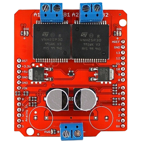
The Monster Moto Shield, manufactured by SparkFun (Part ID: Monster Moto Shield), is a high-power motor driver shield designed for Arduino. It is capable of driving DC motors and stepper motors with ease, making it ideal for robotics, automation, and other motor control applications. The shield features built-in protection mechanisms, such as thermal shutdown and overcurrent protection, ensuring safe and reliable operation. Its plug-and-play design allows for seamless integration with Arduino boards, making it a popular choice for hobbyists and professionals alike.
Explore Projects Built with Monster Moto shield

Explore Projects Built with Monster Moto shield
Common Applications
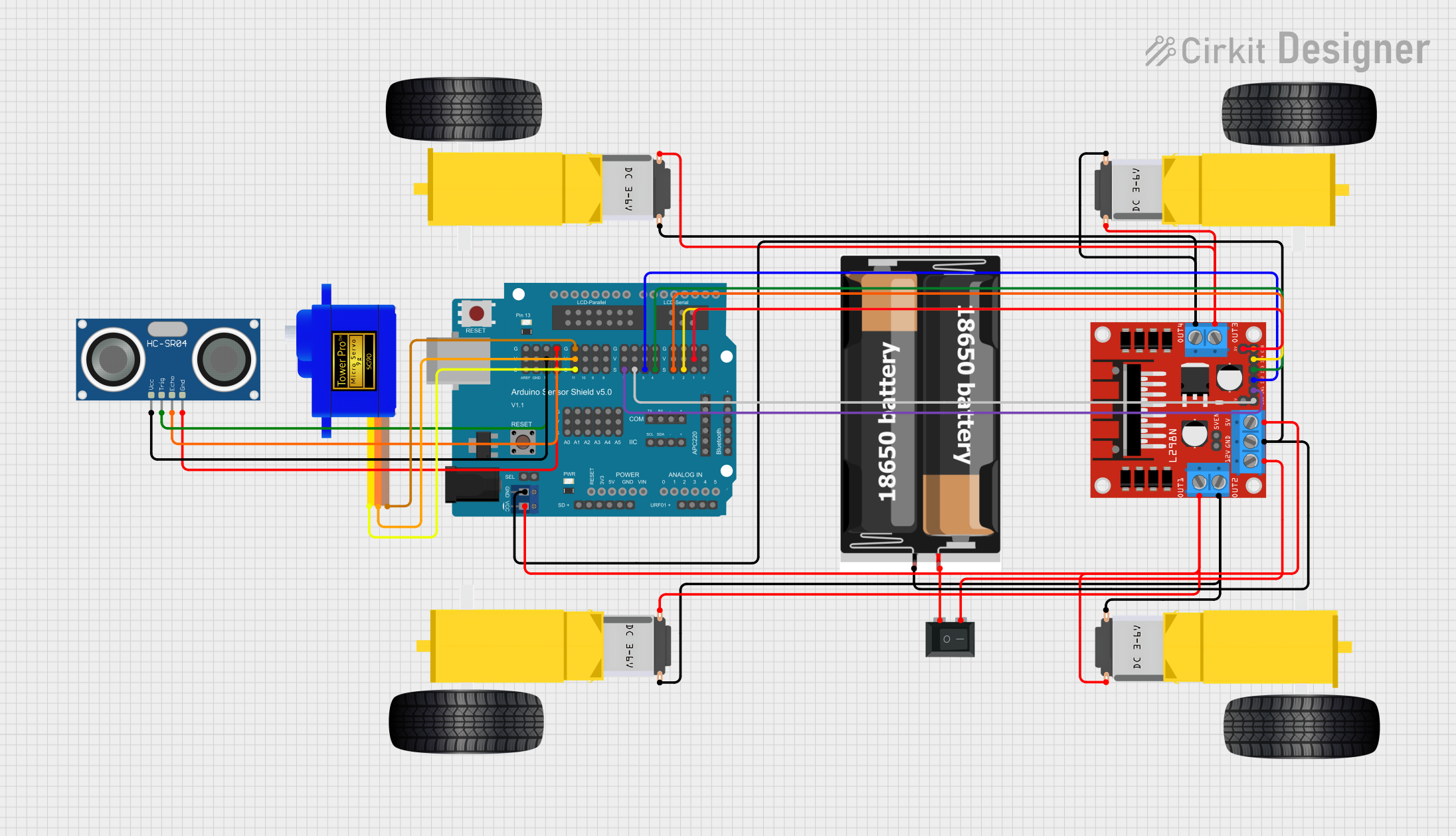
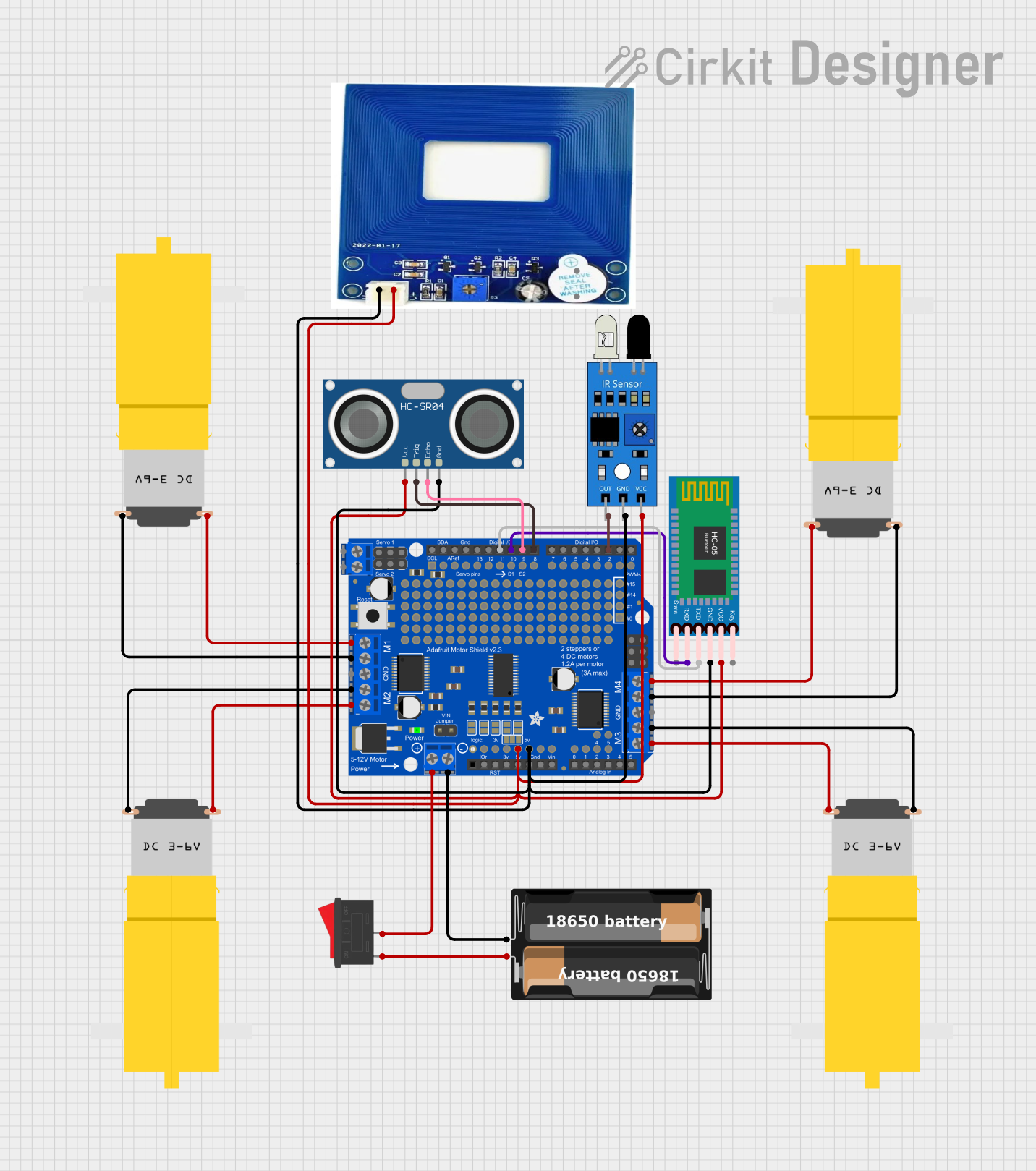
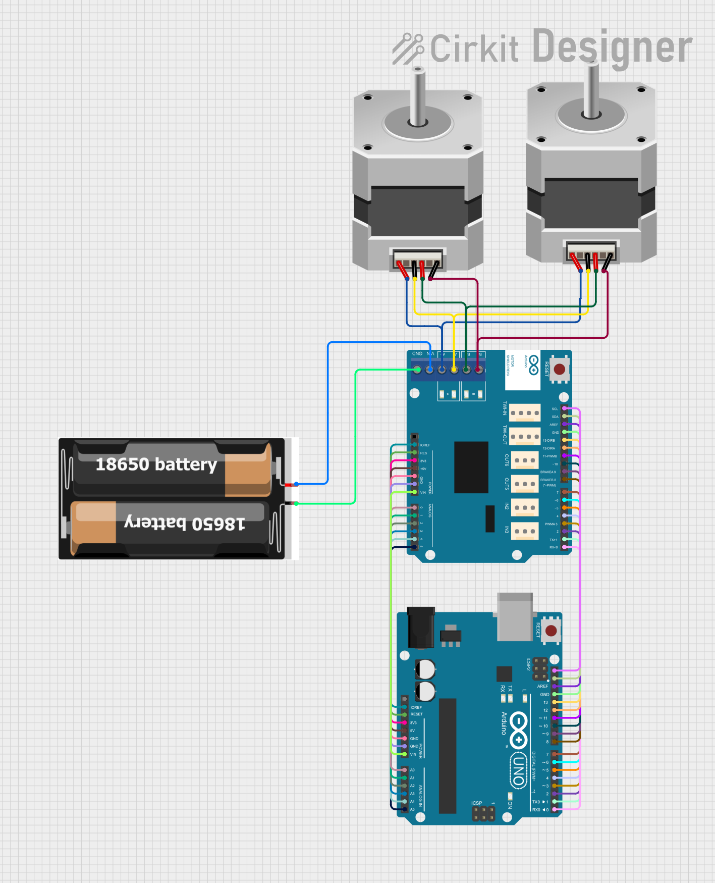
- Robotics and automation projects
- Remote-controlled vehicles
- Conveyor belt systems
- CNC machines and 3D printers
- High-power motor control in industrial applications
Technical Specifications
The Monster Moto Shield is based on the VNH2SP30 motor driver ICs, which provide robust performance for high-power motor control. Below are the key technical details:
| Parameter | Specification |
|---|---|
| Operating Voltage | 5V (logic) / 5.5V–16V (motor supply) |
| Continuous Current per Channel | 14A (max) |
| Peak Current per Channel | 30A (for short durations) |
| PWM Frequency | Up to 20 kHz |
| Motor Channels | 2 (independent or combined) |
| Logic Level Compatibility | 3.3V and 5V |
| Protection Features | Thermal shutdown, overcurrent, undervoltage |
| Dimensions | 68.6mm x 53.3mm |
Pin Configuration and Descriptions
The Monster Moto Shield connects directly to an Arduino board via its headers. Below is the pin configuration:
| Pin | Description |
|---|---|
| D3 (PWM A) | PWM input for Motor A |
| D11 (PWM B) | PWM input for Motor B |
| D12 (DIR A) | Direction control for Motor A |
| D13 (DIR B) | Direction control for Motor B |
| A0 (CS A) | Current sense output for Motor A |
| A1 (CS B) | Current sense output for Motor B |
| VIN | Motor power supply (5.5V–16V) |
| GND | Ground connection |
Usage Instructions
Connecting the Monster Moto Shield
- Mount the Shield: Place the Monster Moto Shield on top of an Arduino board, ensuring the headers align correctly.
- Power the Motors: Connect an external power supply (5.5V–16V) to the VIN and GND terminals on the shield.
- Connect the Motors: Attach the DC motors or stepper motors to the output terminals labeled "Motor A" and "Motor B."
- Set Up the Code: Use the Arduino IDE to upload motor control code to the Arduino board.
Example Code for Arduino UNO
Below is an example code snippet to control two DC motors using the Monster Moto Shield:
// Monster Moto Shield Example Code
// Controls two DC motors using PWM and direction pins

// Define motor control pins
#define PWM_A 3    // PWM pin for Motor A
#define DIR_A 12   // Direction pin for Motor A
#define PWM_B 11   // PWM pin for Motor B
#define DIR_B 13   // Direction pin for Motor B

void setup() {
  // Set motor control pins as outputs
  pinMode(PWM_A, OUTPUT);
  pinMode(DIR_A, OUTPUT);
  pinMode(PWM_B, OUTPUT);
  pinMode(DIR_B, OUTPUT);
}

void loop() {
  // Motor A: Forward at 50% speed
  digitalWrite(DIR_A, HIGH);  // Set direction to forward
  analogWrite(PWM_A, 128);   // Set speed (0–255)

  // Motor B: Reverse at 75% speed
  digitalWrite(DIR_B, LOW);  // Set direction to reverse
  analogWrite(PWM_B, 192);   // Set speed (0–255)

  delay(2000);  // Run motors for 2 seconds

  // Stop both motors
  analogWrite(PWM_A, 0);
  analogWrite(PWM_B, 0);

  delay(1000);  // Wait for 1 second
}
Important Considerations
- Power Supply: Ensure the motor power supply voltage is within the specified range (5.5V–16V).
- Heat Dissipation: The shield may heat up during operation. Use a heatsink or active cooling for high-current applications.
- Current Sensing: Use the CS pins (A0 and A1) to monitor motor current for diagnostics or feedback control.
- PWM Frequency: For optimal performance, use a PWM frequency of up to 20 kHz.
Troubleshooting and FAQs
Common Issues and Solutions
Motors Not Running
- Cause: Incorrect wiring or insufficient power supply.
- Solution: Double-check all connections and ensure the power supply meets the voltage and current requirements.
Overheating
- Cause: Prolonged operation at high currents without proper cooling.
- Solution: Add a heatsink or fan to the shield to improve heat dissipation.
Erratic Motor Behavior
- Cause: Noise or interference in the PWM signal.
- Solution: Use shielded cables for motor connections and ensure a stable power supply.
Arduino Not Responding
- Cause: Excessive current draw or short circuit.
- Solution: Check for short circuits in the motor wiring and ensure the current draw is within limits.
FAQs
Q: Can the Monster Moto Shield drive stepper motors?
A: Yes, the shield can drive stepper motors by controlling the two motor channels independently. You will need to implement stepper motor control logic in your code.
Q: What is the maximum current the shield can handle?
A: The shield can handle up to 14A continuous current per channel and 30A peak current for short durations.
Q: Is the shield compatible with 3.3V logic boards?
A: Yes, the Monster Moto Shield is compatible with both 3.3V and 5V logic levels.
Q: How do I monitor motor current?
A: Use the CS pins (A0 for Motor A and A1 for Motor B) to read the current sense voltage, which is proportional to the motor current.
By following this documentation, you can effectively use the Monster Moto Shield in your projects and troubleshoot common issues with ease.