Cirkit Designer Logo
Cirkit Designer
Your all-in-one circuit design IDE
Home / 
Component Documentation

How to Use IRLML6402: Examples, Pinouts, and Specs

Image of IRLML6402
Cirkit Designer LogoDesign with IRLML6402 in Cirkit Designer

Introduction

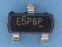
The IRLML6402 is an N-channel MOSFET manufactured by Infineon, with the part ID IRLML6402TRPbF. This component is designed for low-voltage applications and is known for its low on-resistance and fast switching speeds. It is commonly used in power management, load switching, and DC-DC converter circuits. Its compact SOT-23 package makes it ideal for space-constrained designs.

Explore Projects Built with IRLML6402

Use Cirkit Designer to design, explore, and prototype these projects online. Some projects support real-time simulation. Click "Open Project" to start designing instantly!
Arduino Nano-Based SMS Alert System with IR Sensor and SIM800L
Image of GSM Based Door Security system: A project utilizing IRLML6402 in a practical application
This circuit is designed to interface an Arduino Nano with an IR sensor for input, a SIM800L module for GSM communication, and an I2C LCD screen for output display. It includes a 3.7V battery with a TP4056 charging module and a PowerBoost 1000 Basic for power management. The Arduino's code is currently a placeholder, suggesting that the user-defined functionality is pending.
Cirkit Designer LogoOpen Project in Cirkit Designer
Lilygo 7670e-Based Smart Interface with LCD Display and Keypad
Image of Paower: A project utilizing IRLML6402 in a practical application
This circuit features a Lilygo 7670e microcontroller interfaced with a 16x2 I2C LCD for display, a 4X4 membrane matrix keypad for input, and an arcade button for additional control. It also includes a 4G antenna and a GPS antenna for communication and location tracking capabilities.
Cirkit Designer LogoOpen Project in Cirkit Designer
RTL8720DN-Based Interactive Button-Controlled TFT Display
Image of coba-coba: A project utilizing IRLML6402 in a practical application
This circuit features an RTL8720DN microcontroller interfaced with a China ST7735S 160x128 TFT LCD display and four pushbuttons. The microcontroller reads the states of the pushbuttons and displays their statuses on the TFT LCD, providing a visual feedback system for button presses.
Cirkit Designer LogoOpen Project in Cirkit Designer
ESP8266 and SIM800L Based GPS Tracker with I2C LCD Display and Battery Power
Image of Little Innovator Competition: A project utilizing IRLML6402 in a practical application
This circuit integrates an ESP8266 NodeMCU microcontroller with a SIM800L GSM module, a GPS NEO 6M module, and a 16x2 I2C LCD display for communication and location tracking. It also includes a pushbutton for user input, a piezo buzzer for audio alerts, and is powered by a 2x 18650 battery pack through an LM2596 step-down module.
Cirkit Designer LogoOpen Project in Cirkit Designer

Explore Projects Built with IRLML6402

Use Cirkit Designer to design, explore, and prototype these projects online. Some projects support real-time simulation. Click "Open Project" to start designing instantly!
Image of GSM Based Door Security system: A project utilizing IRLML6402 in a practical application
Arduino Nano-Based SMS Alert System with IR Sensor and SIM800L
This circuit is designed to interface an Arduino Nano with an IR sensor for input, a SIM800L module for GSM communication, and an I2C LCD screen for output display. It includes a 3.7V battery with a TP4056 charging module and a PowerBoost 1000 Basic for power management. The Arduino's code is currently a placeholder, suggesting that the user-defined functionality is pending.
Cirkit Designer LogoOpen Project in Cirkit Designer
Image of Paower: A project utilizing IRLML6402 in a practical application
Lilygo 7670e-Based Smart Interface with LCD Display and Keypad
This circuit features a Lilygo 7670e microcontroller interfaced with a 16x2 I2C LCD for display, a 4X4 membrane matrix keypad for input, and an arcade button for additional control. It also includes a 4G antenna and a GPS antenna for communication and location tracking capabilities.
Cirkit Designer LogoOpen Project in Cirkit Designer
Image of coba-coba: A project utilizing IRLML6402 in a practical application
RTL8720DN-Based Interactive Button-Controlled TFT Display
This circuit features an RTL8720DN microcontroller interfaced with a China ST7735S 160x128 TFT LCD display and four pushbuttons. The microcontroller reads the states of the pushbuttons and displays their statuses on the TFT LCD, providing a visual feedback system for button presses.
Cirkit Designer LogoOpen Project in Cirkit Designer
Image of Little Innovator Competition: A project utilizing IRLML6402 in a practical application
ESP8266 and SIM800L Based GPS Tracker with I2C LCD Display and Battery Power
This circuit integrates an ESP8266 NodeMCU microcontroller with a SIM800L GSM module, a GPS NEO 6M module, and a 16x2 I2C LCD display for communication and location tracking. It also includes a pushbutton for user input, a piezo buzzer for audio alerts, and is powered by a 2x 18650 battery pack through an LM2596 step-down module.
Cirkit Designer LogoOpen Project in Cirkit Designer

Common Applications

  • Power management in portable devices
  • Load switching in low-voltage circuits
  • DC-DC converters
  • Motor control in small electronic systems
  • LED drivers

Technical Specifications

Key Electrical Characteristics

Parameter Value Unit
Drain-Source Voltage (VDS) -20 V
Gate-Source Voltage (VGS) ±12 V
Continuous Drain Current (ID) -3.7 (at VGS = -4.5V, TA = 25°C) A
Pulsed Drain Current (IDM) -11 A
Power Dissipation (PD) 1.25 W
RDS(on) (On-Resistance) 0.045 (at VGS = -4.5V, ID = -3.7A) Ω
Operating Temperature Range -55 to +150 °C

Pin Configuration

The IRLML6402 is housed in a 3-pin SOT-23 package. The pinout is as follows:

Pin Number Pin Name Description
1 Gate Controls the MOSFET switching
2 Source Connected to the negative side of the load or ground
3 Drain Connected to the load or power supply

Usage Instructions

How to Use the IRLML6402 in a Circuit

  1. Gate Control: Apply a voltage to the Gate (Pin 1) to control the MOSFET. A negative voltage (e.g., -4.5V) is required to fully turn on the MOSFET.
  2. Drain-Source Connection: Connect the load between the Drain (Pin 3) and the positive supply voltage. The Source (Pin 2) should be connected to the ground or the negative side of the circuit.
  3. Current Handling: Ensure the current through the MOSFET does not exceed the maximum continuous drain current (-3.7A) to avoid damage.
  4. Heat Dissipation: Use proper heat sinking or PCB design to manage power dissipation, especially in high-current applications.

Important Considerations

  • Gate Drive Voltage: Ensure the Gate-Source voltage (VGS) does not exceed ±12V to prevent damage to the MOSFET.
  • Switching Speed: The IRLML6402 is optimized for fast switching. Minimize parasitic inductance and capacitance in the circuit for optimal performance.
  • Protection: Use a flyback diode across inductive loads to protect the MOSFET from voltage spikes during switching.

Example: Using IRLML6402 with Arduino UNO

The IRLML6402 can be used to control a small DC motor with an Arduino UNO. Below is an example circuit and code:

Circuit Connections

  • Connect the Source (Pin 2) to ground.
  • Connect the Drain (Pin 3) to one terminal of the motor. The other terminal of the motor connects to the positive supply voltage.
  • Connect the Gate (Pin 1) to a PWM-capable pin on the Arduino (e.g., Pin 9) through a 220Ω resistor.

Arduino Code

// Example code to control a DC motor using IRLML6402 and Arduino UNO
const int motorPin = 9; // PWM pin connected to the Gate of IRLML6402

void setup() {
  pinMode(motorPin, OUTPUT); // Set motorPin as an output
}

void loop() {
  analogWrite(motorPin, 128); // Set motor speed to 50% (PWM duty cycle = 128/255)
  delay(5000);               // Run motor for 5 seconds
  
  analogWrite(motorPin, 0);  // Turn off the motor
  delay(5000);               // Wait for 5 seconds
}

Troubleshooting and FAQs

Common Issues

  1. MOSFET Not Turning On

    • Ensure the Gate-Source voltage (VGS) is within the recommended range (-4.5V or higher in magnitude).
    • Check for proper connections and ensure the Gate is not left floating.
  2. Excessive Heat

    • Verify that the current through the MOSFET does not exceed the maximum continuous drain current (-3.7A).
    • Ensure proper heat dissipation through PCB design or external heat sinks.
  3. Motor Not Running

    • Check the PWM signal from the Arduino. Use a multimeter or oscilloscope to verify the output.
    • Ensure the power supply voltage is sufficient for the motor and the MOSFET.

FAQs

Q: Can the IRLML6402 handle inductive loads like motors?
A: Yes, but you should use a flyback diode across the load to protect the MOSFET from voltage spikes during switching.

Q: What is the maximum Gate-Source voltage?
A: The maximum Gate-Source voltage is ±12V. Exceeding this value may damage the MOSFET.

Q: Can I use the IRLML6402 for high-frequency switching?
A: Yes, the IRLML6402 is designed for fast switching applications. Ensure your circuit minimizes parasitic inductance and capacitance for optimal performance.