How to Use Resettable Fuse PTC: Examples, Pinouts, and Specs

Introduction
A Resettable Fuse PTC (Positive Temperature Coefficient) is a passive electronic component that serves as a self-resetting overcurrent protection device. Unlike traditional fuses, which must be replaced after a single use, a PTC resettable fuse will return to a low-resistance state after the overcurrent condition has been removed and the device has cooled down. This makes them ideal for protecting sensitive electronic circuits against short circuits or excessive current draw without the need for maintenance or replacement after a fault.
Explore Projects Built with Resettable Fuse PTC


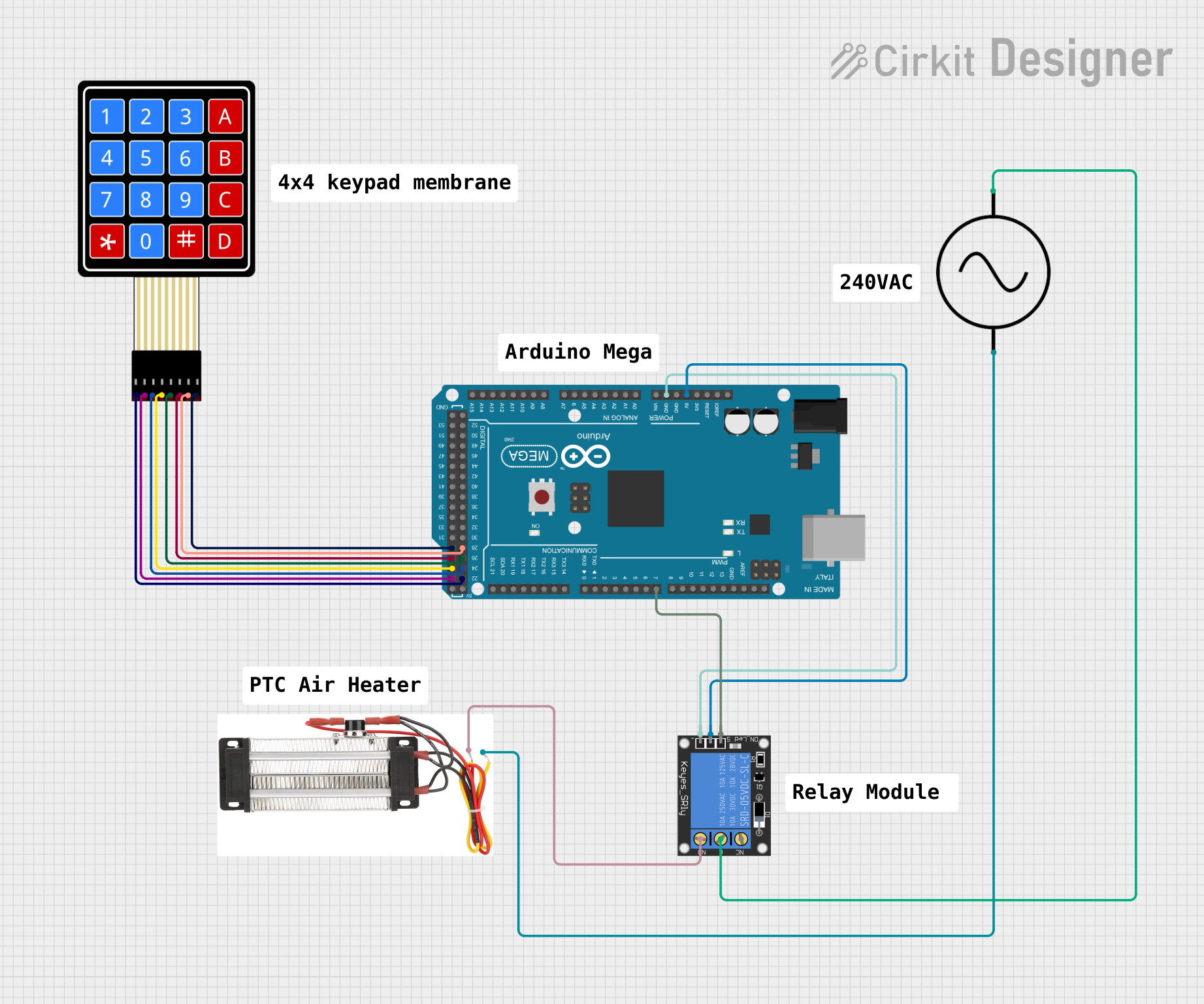
Explore Projects Built with Resettable Fuse PTC
Common Applications and Use Cases
- USB ports and peripherals
- Battery packs
- Power supplies
- Automotive electronics
- Consumer electronics such as mobile phones, PCs, and game consoles
Technical Specifications
Key Technical Details
- Voltage Rating: The maximum voltage the PTC can withstand without damage.
- Current Rating: The nominal operating current before the PTC trips.
- Trip Current: The current at which the PTC will transition to a high-resistance state.
- Time to Trip: The time it takes for the PTC to trip at a specified current.
- Resistance: The resistance of the PTC in its normal (low-resistance) and tripped (high-resistance) states.
- Power Rating: The maximum power the PTC can dissipate without damage.
Pin Configuration and Descriptions
| Pin Number | Description |
|---|---|
| 1 | First terminal |
| 2 | Second terminal |
Note: PTC resettable fuses are typically two-terminal devices, similar to standard fuses.
Usage Instructions
How to Use the Component in a Circuit
- Identify the Correct PTC: Choose a PTC with a voltage rating above the maximum operating voltage and a current rating that matches the nominal current of the circuit.
- Circuit Placement: Install the PTC in series with the load that needs protection.
- Soldering: If applicable, solder the PTC to the PCB, ensuring not to exceed the recommended soldering temperature and duration to prevent damage to the PTC.
Important Considerations and Best Practices
- Selecting PTC: Ensure the trip current is sufficiently above the normal operating current to prevent nuisance tripping.
- Thermal Considerations: Provide adequate spacing around the PTC to allow for proper cooling.
- Recovery Time: Allow time for the PTC to cool down and reset after a trip event.
- Testing: Test the circuit with the PTC installed to ensure it trips under fault conditions and resets appropriately.
Troubleshooting and FAQs
Common Issues
- PTC Does Not Reset: Ensure the fault condition has been cleared and the PTC has had enough time to cool down.
- Nuisance Tripping: If the PTC trips during normal operation, verify that the selected PTC's current rating is appropriate for the circuit.
Solutions and Tips for Troubleshooting
- Check Connections: Ensure the PTC is properly connected in series with the load.
- Inspect for Damage: Look for signs of physical damage or discoloration on the PTC, which may indicate it has been subjected to excessive current or voltage.
- Measure Resistance: In its normal state, the PTC should have a low resistance. A high resistance in this state may indicate a fault.
FAQs
Q: Can a PTC be used multiple times? A: Yes, PTCs are designed to reset themselves after a fault is cleared and the device cools down.
Q: How quickly does a PTC reset? A: The reset time can vary based on the severity of the overcurrent condition and the ambient temperature. It can range from a few seconds to several minutes.
Q: Is there any maintenance required for a PTC? A: No, PTCs are maintenance-free, but it's important to periodically check the circuit for proper operation.
Example Code for Arduino UNO
// Example code to demonstrate the use of a PTC with an Arduino UNO
// This code assumes a PTC is used to protect a simple LED circuit

const int ledPin = 13; // LED connected to digital pin 13

void setup() {
  pinMode(ledPin, OUTPUT); // Initialize the digital pin as an output
}

void loop() {
  digitalWrite(ledPin, HIGH); // Turn the LED on
  delay(1000);                // Wait for 1 second
  digitalWrite(ledPin, LOW);  // Turn the LED off
  delay(1000);                // Wait for 1 second
}

// Note: The PTC would be placed in series with the LED on the breadboard,
// not directly controlled by the Arduino code. The code is provided to
// demonstrate a typical use case where the PTC would protect the LED from
// excessive current, for example, if a wrong resistor value was used.
Remember to wrap the PTC around the LED circuit on the breadboard, not through the Arduino directly. The code is for illustrative purposes to show a typical application where the PTC provides protection.