How to Use Traffic Light: Examples, Pinouts, and Specs
Introduction
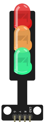
A traffic light is a signaling device that uses colored lights—red, yellow, and green—to control traffic flow at intersections. These lights indicate stop, caution, and go, respectively, ensuring safe and orderly movement of vehicles and pedestrians. Traffic lights are widely used in urban areas, highways, and pedestrian crossings to manage traffic efficiently and reduce accidents.
Explore Projects Built with Traffic Light
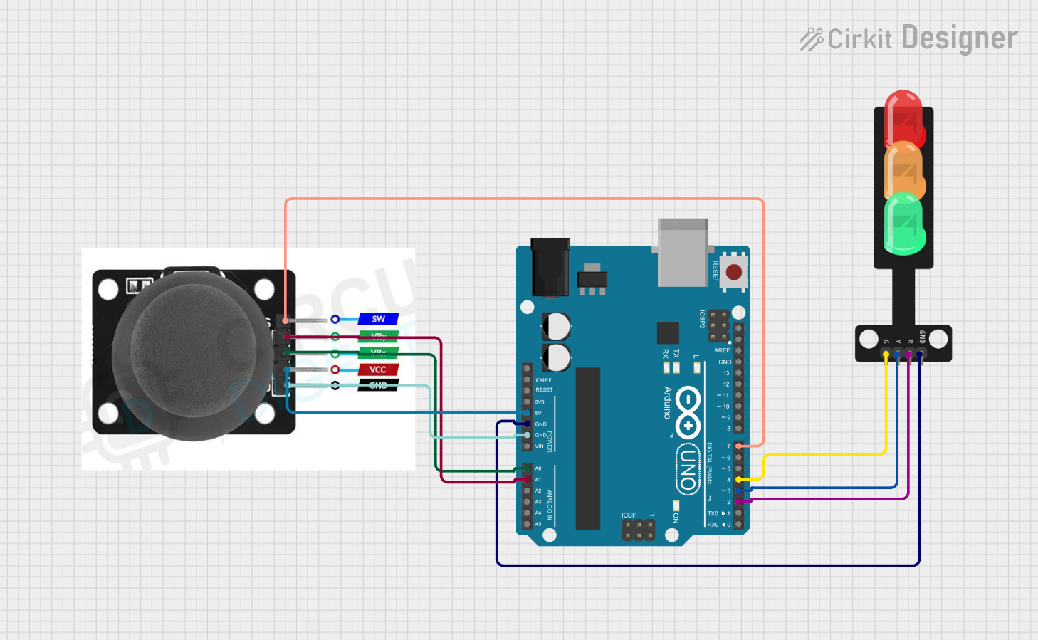
Explore Projects Built with Traffic Light
Common Applications and Use Cases
- Traffic control at road intersections
- Pedestrian crossings
- Vehicle flow management in parking lots
- Simulated traffic systems for educational purposes
- Integration into smart city infrastructure
Technical Specifications
Key Technical Details
- Operating Voltage: Typically 5V to 12V DC (depending on the design)
- Current Consumption: ~20mA per LED (varies by LED type)
- Light Colors: Red, Yellow, Green
- LED Type: High-brightness LEDs for visibility
- Control Method: Microcontroller or relay-based switching
- Dimensions: Varies by model (e.g., 3-light module: ~10cm x 3cm x 3cm)
Pin Configuration and Descriptions
Below is a typical pin configuration for a 3-light traffic light module:
| Pin | Name | Description |
|---|---|---|
| 1 | Red LED (+) | Positive terminal for the red LED (connect to microcontroller or power source) |
| 2 | Yellow LED (+) | Positive terminal for the yellow LED (connect to microcontroller or power source) |
| 3 | Green LED (+) | Positive terminal for the green LED (connect to microcontroller or power source) |
| 4 | Common (-) | Common ground for all LEDs (connect to ground of the circuit) |
Usage Instructions
How to Use the Component in a Circuit
- Power Supply: Ensure the traffic light module is powered with the appropriate voltage (e.g., 5V or 12V DC). Check the module's datasheet for exact requirements.
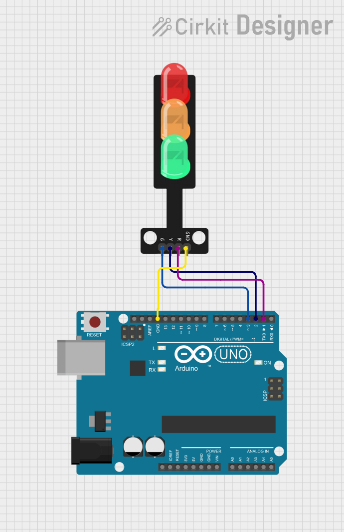
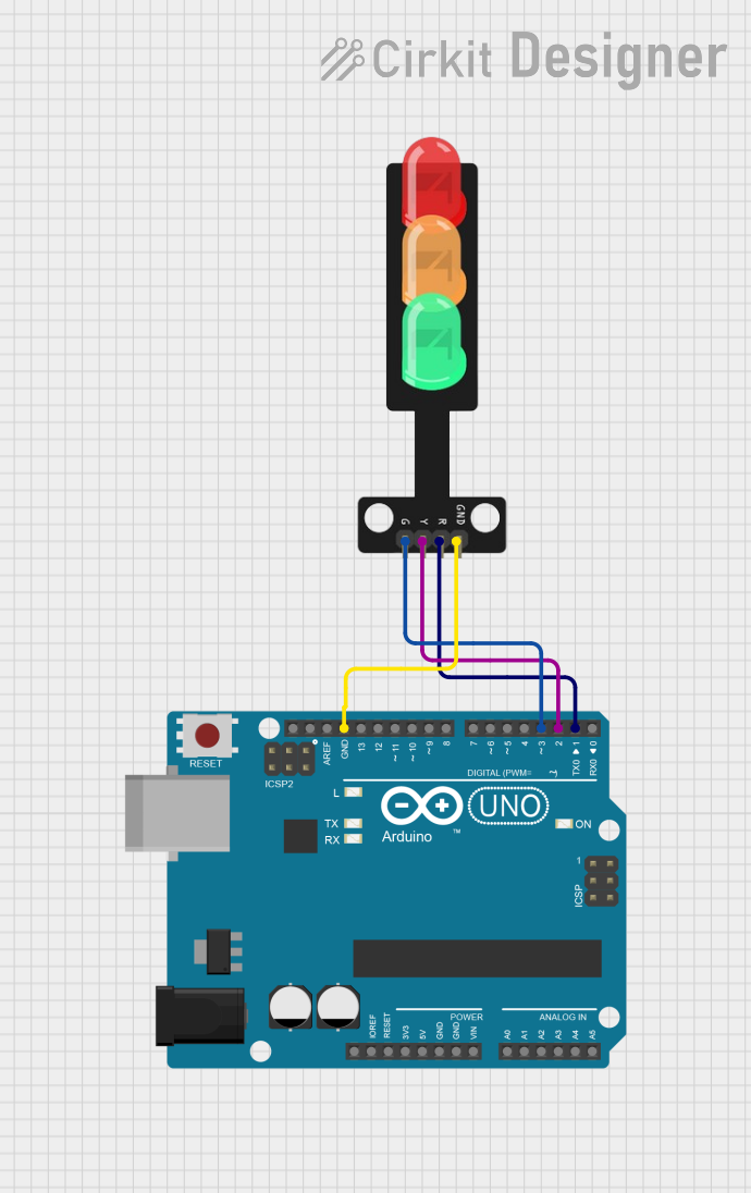
- Connections:
- Connect the red, yellow, and green LED pins to the respective control pins of a microcontroller (e.g., Arduino UNO) or a switching circuit.
- Connect the common ground pin to the ground of the power supply or microcontroller.
- Control Logic:
- Use a microcontroller to control the LEDs based on a timing sequence (e.g., red for 10 seconds, yellow for 3 seconds, green for 10 seconds).
- Alternatively, use a timer circuit (e.g., 555 timer IC) for standalone operation.
Important Considerations and Best Practices
- Resistors: Always use current-limiting resistors in series with each LED to prevent damage. Calculate the resistor value based on the LED's forward voltage and desired current.
- Visibility: Ensure the traffic light is placed in a location with clear visibility for users.
- Power Supply: Use a stable power supply to avoid flickering or inconsistent operation.
- Heat Management: If the module operates for extended periods, ensure proper ventilation to prevent overheating.
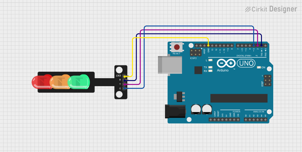
Example: Connecting to an Arduino UNO
Below is an example of how to control a traffic light module using an Arduino UNO:
// Pin assignments for the traffic light module
const int redPin = 8;    // Red LED connected to digital pin 8
const int yellowPin = 9; // Yellow LED connected to digital pin 9
const int greenPin = 10; // Green LED connected to digital pin 10

void setup() {
  // Set the LED pins as outputs
  pinMode(redPin, OUTPUT);
  pinMode(yellowPin, OUTPUT);
  pinMode(greenPin, OUTPUT);
}

void loop() {
  // Red light ON for 10 seconds
  digitalWrite(redPin, HIGH);
  digitalWrite(yellowPin, LOW);
  digitalWrite(greenPin, LOW);
  delay(10000); // Wait for 10 seconds

  // Yellow light ON for 3 seconds
  digitalWrite(redPin, LOW);
  digitalWrite(yellowPin, HIGH);
  digitalWrite(greenPin, LOW);
  delay(3000); // Wait for 3 seconds

  // Green light ON for 10 seconds
  digitalWrite(redPin, LOW);
  digitalWrite(yellowPin, LOW);
  digitalWrite(greenPin, HIGH);
  delay(10000); // Wait for 10 seconds
}
Troubleshooting and FAQs
Common Issues and Solutions
LEDs Not Lighting Up:
- Check the power supply voltage and ensure it matches the module's requirements.
- Verify all connections, especially the ground connection.
- Ensure current-limiting resistors are correctly installed.
Flickering LEDs:
- Use a stable power supply with sufficient current capacity.
- Check for loose connections or faulty wires.
Incorrect LED Sequence:
- Double-check the control logic in your microcontroller code.
- Ensure the correct pins are connected to the respective LEDs.
Overheating:
- Verify that the current through each LED does not exceed its rated value.
- Use appropriate resistors to limit current.
FAQs
Q: Can I use the traffic light module with a 3.3V microcontroller?
A: Yes, but ensure the LEDs can operate at 3.3V. If not, use a transistor or MOSFET to drive the LEDs with a higher voltage.
Q: How do I calculate the resistor value for the LEDs?
A: Use the formula:
R = (V_supply - V_forward) / I_forward
Where V_supply is the power supply voltage, V_forward is the LED's forward voltage, and I_forward is the desired current (e.g., 20mA).
Q: Can I use this module outdoors?
A: Most traffic light modules are designed for indoor use. For outdoor applications, ensure the module is weatherproof or housed in a protective enclosure.