How to Use raspberry pi pico w: Examples, Pinouts, and Specs
Introduction
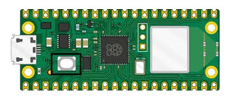
The Raspberry Pi Pico W is a highly versatile microcontroller board that builds upon the standard Raspberry Pi Pico by adding WiFi connectivity. Based on the powerful RP2040 chip developed by Raspberry Pi, the Pico W is designed for hobbyists, educators, and professionals who require a compact, cost-effective platform for Internet of Things (IoT) projects, embedded systems, and prototyping.
Explore Projects Built with raspberry pi pico w
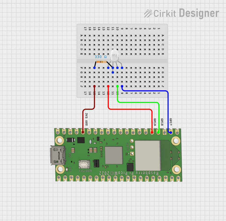
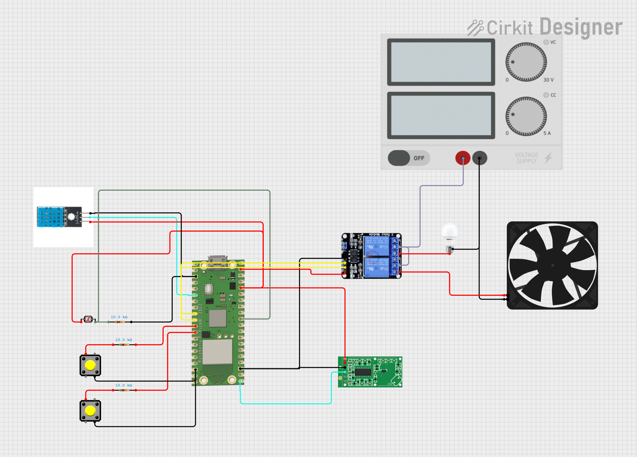
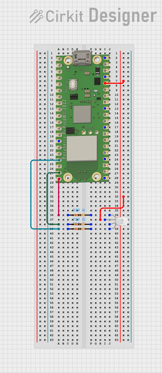

Explore Projects Built with raspberry pi pico w
Common Applications and Use Cases
- IoT devices and sensors
- Home automation systems
- Wireless data loggers
- Educational projects and learning platforms
- Prototyping for embedded systems
Technical Specifications
Key Technical Details
- Chip: RP2040 microcontroller chip designed by Raspberry Pi
- CPU: Dual-core Arm Cortex-M0+ processor, flexible clock running up to 133 MHz
- Memory: 264KB of SRAM, and 2MB of on-board Flash memory
- Wireless Connectivity: 2.4GHz 802.11n wireless LAN
- Input Voltage (VIN): 1.8V to 5.5V
- GPIO: 26 multi-function GPIO pins
- ADC: Three ADC channels with 12-bit resolution
- Interfaces: UART, SPI, I2C, PWM, and USB 1.1
Pin Configuration and Descriptions
| Pin Number | Name | Description |
|---|---|---|
| 1 | GP0 | General-purpose I/O and UART0 TX |
| 2 | GP1 | General-purpose I/O and UART0 RX |
| ... | ... | ... |
| 40 | VBUS | USB input voltage |
Note: This table is not exhaustive and only shows a sample of the pin configuration.
Usage Instructions
How to Use the Component in a Circuit
- Powering the Pico W: Apply power through the micro-USB port or the VSYS/GND pins.
- Connecting to WiFi: Utilize the onboard wireless LAN to connect to a network for IoT applications.
- Programming the Pico W: Use languages like MicroPython or C/C++ to write and upload code.
Important Considerations and Best Practices
- Ensure that the input voltage does not exceed the recommended range to prevent damage.
- Use proper ESD precautions when handling the Pico W to avoid static damage to the board.
- When designing a circuit, consider the current limitations of the GPIO pins and the board itself.
- For wireless applications, place the Pico W away from large metal surfaces to minimize interference.
Troubleshooting and FAQs
Common Issues Users Might Face
- WiFi Connectivity Problems: Ensure the network credentials are correct and the signal strength is adequate.
- Power Issues: Verify that the power supply is within the specified range and the connections are secure.
- Programming Errors: Check for syntax errors or incorrect use of libraries in your code.
Solutions and Tips for Troubleshooting
- Resetting the Board: If the Pico W becomes unresponsive, try resetting it by momentarily connecting the RUN pin to GND.
- Updating Firmware: Keep the Pico W's firmware up to date to ensure compatibility with the latest features and fixes.
- Consulting Documentation: Refer to the official Raspberry Pi Pico W documentation for in-depth troubleshooting guides.
Example Code for Arduino UNO Connectivity
// This example demonstrates how to toggle an LED on the Pico W using an Arduino UNO.
// The Pico W is programmed to listen for serial commands from the Arduino UNO to control the LED.

#include <Arduino.h>

// Define the LED pin and serial command
const int ledPin = 25; // GPIO 25 on the Pico W
const char toggleCommand = 't';

void setup() {
  // Initialize the LED pin as an output
  pinMode(ledPin, OUTPUT);
  // Begin serial communication at 9600 baud rate
  Serial.begin(9600);
}

void loop() {
  // Check if data is available to read from the serial port
  if (Serial.available() > 0) {
    // Read the incoming byte
    char receivedChar = Serial.read();
    // Check if the received command is the toggle command
    if (receivedChar == toggleCommand) {
      // Toggle the LED state
      digitalWrite(ledPin, !digitalRead(ledPin));
    }
  }
}
Note: This code is written for the Pico W and assumes that it is connected to an Arduino UNO via a serial connection. The Arduino UNO would need to send the 't' character to toggle the LED on the Pico W.
Remember to consult the official Raspberry Pi Pico W documentation for more detailed information and additional resources. This documentation is intended to provide a starting point for working with the Pico W and may not cover all aspects of its use.