
How to Use 57AM23ED Stepper Servo Motor: Examples, Pinouts, and Specs
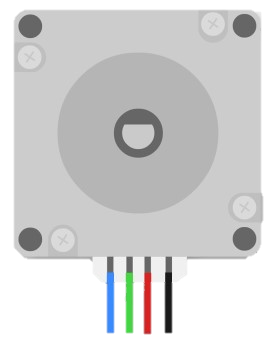
 Design with 57AM23ED Stepper Servo Motor in Cirkit Designer
Introduction
The 57AM23ED Stepper Servo Motor, manufactured by Rtelligent, is a high-precision motor that combines the features of a stepper motor and a servo motor. This hybrid design provides accurate position control, high torque at low speeds, and smooth operation. It is ideal for applications requiring precise movement, such as CNC machines, robotics, 3D printers, and automated manufacturing systems.
By integrating the benefits of both stepper and servo technologies, the 57AM23ED offers improved efficiency, reduced noise, and enhanced reliability, making it a versatile choice for demanding motion control tasks.
Explore Projects Built with 57AM23ED Stepper Servo Motor
 Open Project in Cirkit Designer
 Open Project in Cirkit Designer
 Open Project in Cirkit Designer
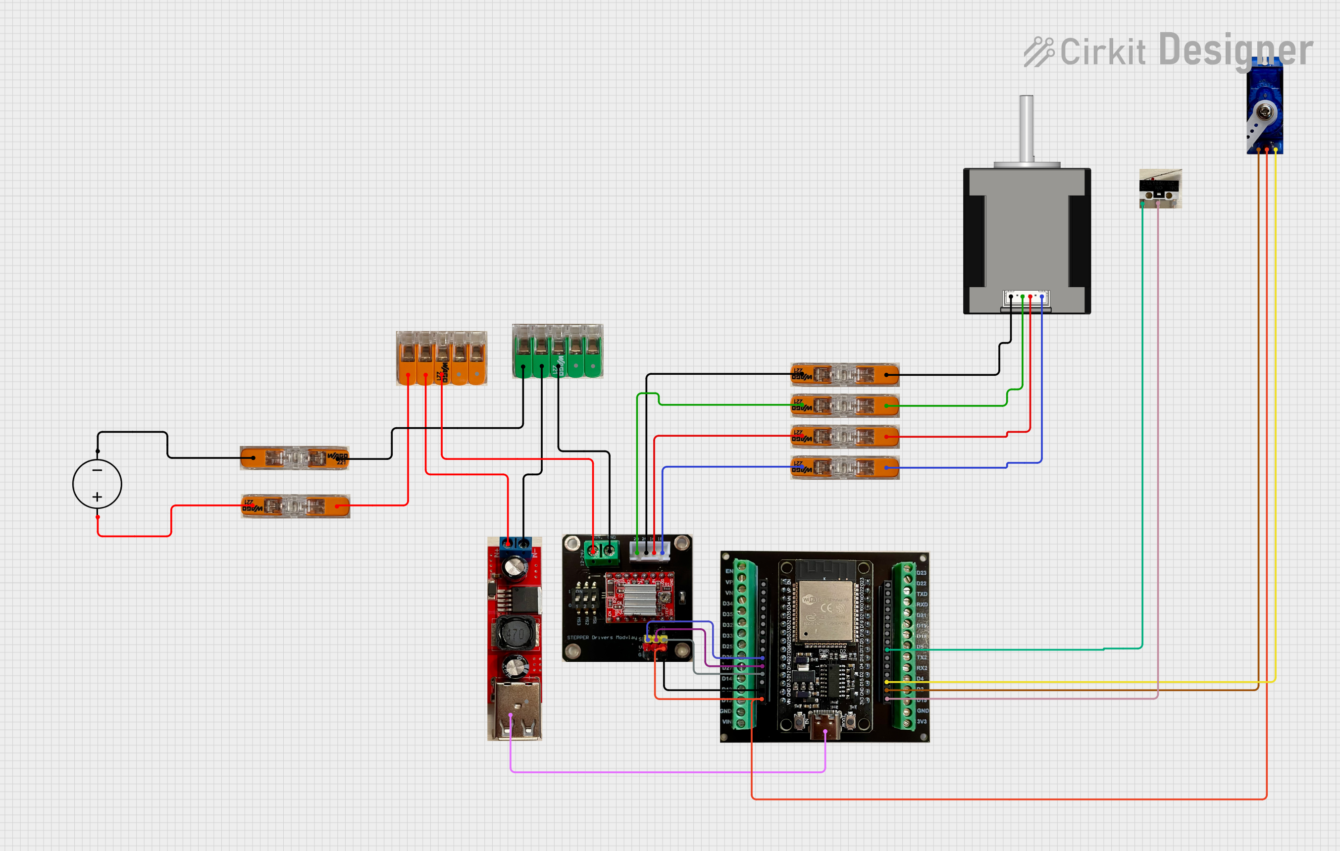 Open Project in Cirkit Designer
Explore Projects Built with 57AM23ED Stepper Servo Motor
Open Project in Cirkit DesignerOpen Project in Cirkit DesignerOpen Project in Cirkit DesignerOpen Project in Cirkit DesignerTechnical Specifications
Below are the key technical details of the 57AM23ED Stepper Servo Motor:
General Specifications
| Parameter | Value |
|---|---|
| Manufacturer | Rtelligent |
| Part Number | 57AM23ED |
| Motor Type | Stepper Servo Motor |
| Step Angle | 1.8° |
| Holding Torque | 2.3 Nm |
| Rated Voltage | 24 V DC |
| Rated Current | 3.5 A |
| Rotor Inertia | 480 g·cm² |
| Maximum Speed | 3000 RPM |
| Operating Temperature | -20°C to +50°C |
| Weight | 1.2 kg |
Pin Configuration and Descriptions
The motor typically comes with a 4-pin or 6-pin connector for interfacing. Below is the pin configuration:
Motor Winding Connections
| Pin Number | Wire Color | Description |
|---|---|---|
| 1 | Red | A+ (Phase A positive) |
| 2 | Blue | A- (Phase A negative) |
| 3 | Green | B+ (Phase B positive) |
| 4 | Black | B- (Phase B negative) |
Encoder Connections (if applicable)
| Pin Number | Wire Color | Description |
|---|---|---|
| 1 | Yellow | Encoder A |
| 2 | White | Encoder B |
| 3 | Orange | Encoder Power (+5V) |
| 4 | Brown | Encoder Ground (GND) |
Usage Instructions
How to Use the 57AM23ED in a Circuit
- Power Supply: Ensure the motor is powered with a stable 24 V DC power supply capable of delivering at least 3.5 A.
- Driver Selection: Use a compatible stepper motor driver or controller that supports closed-loop operation for stepper servo motors. Ensure the driver matches the motor's voltage and current ratings.
- Wiring:
- Connect the motor windings (A+, A-, B+, B-) to the corresponding terminals on the driver.
- If the motor includes an encoder, connect the encoder wires to the driver or microcontroller for feedback.
- Control Signals: Provide step and direction signals from a microcontroller (e.g., Arduino) or a motion controller to the driver.
- Programming: Configure the driver or microcontroller to match the motor's step angle (1.8°) and desired speed/acceleration parameters.
Important Considerations and Best Practices
- Avoid Overheating: Ensure proper ventilation or heat dissipation to prevent the motor from overheating during prolonged operation.
- Current Limiting: Set the driver's current limit to match the motor's rated current (3.5 A) to avoid damage.
- Stable Power Supply: Use a regulated power supply to prevent voltage fluctuations that could affect performance.
- Encoder Calibration: If using the encoder for closed-loop control, ensure it is properly calibrated for accurate feedback.
- Mounting: Securely mount the motor to prevent vibrations or misalignment during operation.
Example: Using the 57AM23ED with an Arduino UNO
Below is an example of how to control the 57AM23ED using an Arduino UNO and a compatible stepper motor driver:
// Example code to control the 57AM23ED Stepper Servo Motor with Arduino UNO
// Ensure the driver is connected to the motor and powered with 24V DC

#define STEP_PIN 3  // Pin connected to the driver's STEP input
#define DIR_PIN 4   // Pin connected to the driver's DIR input

void setup() {
  pinMode(STEP_PIN, OUTPUT); // Set STEP pin as output
  pinMode(DIR_PIN, OUTPUT);  // Set DIR pin as output

  digitalWrite(DIR_PIN, HIGH); // Set direction (HIGH = clockwise, LOW = counterclockwise)
}

void loop() {
  // Generate step pulses to move the motor
  for (int i = 0; i < 200; i++) { // 200 steps = 1 full revolution (1.8° step angle)
    digitalWrite(STEP_PIN, HIGH); // Set STEP pin HIGH
    delayMicroseconds(1000);      // Wait 1 ms (adjust for speed control)
    digitalWrite(STEP_PIN, LOW);  // Set STEP pin LOW
    delayMicroseconds(1000);      // Wait 1 ms
  }

  delay(1000); // Wait 1 second before changing direction

  // Change direction
  digitalWrite(DIR_PIN, !digitalRead(DIR_PIN)); // Toggle direction
}
Troubleshooting and FAQs
Common Issues and Solutions
Motor Not Moving:
- Cause: Incorrect wiring or loose connections.
- Solution: Double-check all connections, especially the motor windings and power supply.
Motor Overheating:
- Cause: Current limit set too high or insufficient ventilation.
- Solution: Reduce the current limit on the driver and ensure proper cooling.
Jerky or Inconsistent Movement:
- Cause: Incorrect step angle or driver configuration.
- Solution: Verify the step angle (1.8°) and ensure the driver settings match the motor specifications.
Encoder Feedback Not Working:
- Cause: Faulty encoder wiring or incorrect calibration.
- Solution: Check the encoder connections and recalibrate if necessary.
FAQs
Can the 57AM23ED operate without an encoder?
- Yes, but using the encoder enables closed-loop control for improved accuracy and performance.
What is the maximum speed of the motor?
- The motor can achieve speeds up to 3000 RPM, depending on the load and driver configuration.
Is the motor compatible with 12 V power supplies?
- No, the motor is designed for 24 V DC operation. Using a lower voltage may result in reduced performance.
What type of driver is recommended for this motor?
- A closed-loop stepper motor driver that supports 24 V and 3.5 A current is recommended for optimal performance.
By following this documentation, users can effectively integrate the 57AM23ED Stepper Servo Motor into their projects and achieve precise motion control.