Cirkit Designer Logo
Cirkit Designer
Your all-in-one circuit design IDE
Home / 
Component Documentation

How to Use Tanauan City College: Examples, Pinouts, and Specs

Image of Tanauan City College
Cirkit Designer LogoDesign with Tanauan City College in Cirkit Designer

Introduction

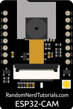
The ESP32-CAM is a low-cost, compact, and versatile Wi-Fi and Bluetooth-enabled microcontroller module with an integrated camera. It is widely used in IoT (Internet of Things) applications, surveillance systems, and image processing projects. The module combines the power of the ESP32 microcontroller with a camera module, making it ideal for projects requiring wireless image capture and processing.

Explore Projects Built with Tanauan City College

Use Cirkit Designer to design, explore, and prototype these projects online. Some projects support real-time simulation. Click "Open Project" to start designing instantly!
Load Cell Signal Conditioning Circuit with Dual Op-Amp and PNP Transistor
Image of Copy of Copy of Circuit with Load Cell Clean: A project utilizing Tanauan City College in a practical application
This analog circuit is designed for signal conditioning of a load cell output using a PNP transistor and a dual operational amplifier (TLC272CP). It includes resistors for biasing and current limiting, and tantalum capacitors for filtering or timing, with a multimeter connected for monitoring voltage and ground connections.
Cirkit Designer LogoOpen Project in Cirkit Designer
Arduino UNO-Based Water Quality Monitoring System with GSM and Solar Power
Image of IOT plankton: A project utilizing Tanauan City College in a practical application
This circuit is a water quality monitoring system powered by a solar panel and a Li-ion battery, featuring an Arduino UNO that collects data from various sensors including TDS, turbidity, pH, and temperature. The collected data is transmitted via a SIM800L GSM module, allowing remote monitoring of water quality parameters.
Cirkit Designer LogoOpen Project in Cirkit Designer
Arduino UNO Bluetooth-Controlled Servo with LDR Feedback
Image of gogo: A project utilizing Tanauan City College in a practical application
This circuit features an Arduino UNO microcontroller interfaced with a Bluetooth HC-06 module for wireless communication, a Tower Pro SG90 servo motor for actuation, and a Module LDR for light intensity sensing. The Arduino controls the servo based on the data received from the LDR or Bluetooth module. The Bluetooth module enables remote control or data exchange, while the LDR provides environmental feedback to the Arduino.
Cirkit Designer LogoOpen Project in Cirkit Designer
Arduino-Controlled Servo with Light Sensing
Image of Servo: A project utilizing Tanauan City College in a practical application
This circuit features an Arduino UNO microcontroller interfaced with two photocells (LDRs) and a servo motor. The photocells are connected to analog inputs A0 and A1, and their average light intensity reading is used to control the position of the servo motor connected to digital pin D9. The circuit is powered by a pair of 18650 Li-ion batteries, which are also connected to a TP4056 charging module that can be charged via a solar cell, providing a renewable energy source for the system.
Cirkit Designer LogoOpen Project in Cirkit Designer

Explore Projects Built with Tanauan City College

Use Cirkit Designer to design, explore, and prototype these projects online. Some projects support real-time simulation. Click "Open Project" to start designing instantly!
Image of Copy of Copy of Circuit with Load Cell Clean: A project utilizing Tanauan City College in a practical application
Load Cell Signal Conditioning Circuit with Dual Op-Amp and PNP Transistor
This analog circuit is designed for signal conditioning of a load cell output using a PNP transistor and a dual operational amplifier (TLC272CP). It includes resistors for biasing and current limiting, and tantalum capacitors for filtering or timing, with a multimeter connected for monitoring voltage and ground connections.
Cirkit Designer LogoOpen Project in Cirkit Designer
Image of IOT plankton: A project utilizing Tanauan City College in a practical application
Arduino UNO-Based Water Quality Monitoring System with GSM and Solar Power
This circuit is a water quality monitoring system powered by a solar panel and a Li-ion battery, featuring an Arduino UNO that collects data from various sensors including TDS, turbidity, pH, and temperature. The collected data is transmitted via a SIM800L GSM module, allowing remote monitoring of water quality parameters.
Cirkit Designer LogoOpen Project in Cirkit Designer
Image of gogo: A project utilizing Tanauan City College in a practical application
Arduino UNO Bluetooth-Controlled Servo with LDR Feedback
This circuit features an Arduino UNO microcontroller interfaced with a Bluetooth HC-06 module for wireless communication, a Tower Pro SG90 servo motor for actuation, and a Module LDR for light intensity sensing. The Arduino controls the servo based on the data received from the LDR or Bluetooth module. The Bluetooth module enables remote control or data exchange, while the LDR provides environmental feedback to the Arduino.
Cirkit Designer LogoOpen Project in Cirkit Designer
Image of Servo: A project utilizing Tanauan City College in a practical application
Arduino-Controlled Servo with Light Sensing
This circuit features an Arduino UNO microcontroller interfaced with two photocells (LDRs) and a servo motor. The photocells are connected to analog inputs A0 and A1, and their average light intensity reading is used to control the position of the servo motor connected to digital pin D9. The circuit is powered by a pair of 18650 Li-ion batteries, which are also connected to a TP4056 charging module that can be charged via a solar cell, providing a renewable energy source for the system.
Cirkit Designer LogoOpen Project in Cirkit Designer

Common Applications and Use Cases

  • Wireless surveillance cameras
  • Smart home automation systems
  • Face recognition and object detection
  • IoT-enabled image processing
  • Remote monitoring and control systems

Technical Specifications

The ESP32-CAM module is equipped with a powerful ESP32 microcontroller and an OV2640 camera. Below are the key technical details:

General Specifications

Parameter Value
Microcontroller ESP32-D0WDQ6
Camera OV2640
Wireless Connectivity Wi-Fi 802.11 b/g/n, Bluetooth
Flash Memory 4 MB (PSRAM)
Operating Voltage 3.3V
Input Voltage Range 5V (via external power supply)
GPIO Pins 9
Dimensions 27mm x 40.5mm

Pin Configuration and Descriptions

The ESP32-CAM module has a total of 16 pins. Below is the pinout and description:

Pin Name Pin Number Description
GND 1 Ground
3.3V 2 3.3V power supply
5V 3 5V power supply
U0R 4 UART0 RX for serial communication
U0T 5 UART0 TX for serial communication
GPIO0 6 General-purpose I/O, used for boot mode selection
GPIO1 7 General-purpose I/O
GPIO2 8 General-purpose I/O
GPIO3 9 General-purpose I/O
GPIO4 10 General-purpose I/O
GPIO12 11 General-purpose I/O
GPIO13 12 General-purpose I/O
GPIO14 13 General-purpose I/O
GPIO15 14 General-purpose I/O
GPIO16 15 General-purpose I/O
RESET 16 Reset pin

Usage Instructions

The ESP32-CAM can be used in a variety of projects. Below are the steps to get started:

Connecting the ESP32-CAM to an Arduino UNO

  1. Power the Module: Connect the 5V and GND pins of the ESP32-CAM to the 5V and GND pins of the Arduino UNO.
  2. Serial Communication: Connect the U0R (RX) pin of the ESP32-CAM to the TX pin of the Arduino UNO, and the U0T (TX) pin of the ESP32-CAM to the RX pin of the Arduino UNO.
  3. Boot Mode: Connect GPIO0 to GND to enable programming mode.
  4. Upload Code: Use the Arduino IDE to upload the code to the ESP32-CAM.

Sample Code for Capturing an Image

Below is a simple example of how to use the ESP32-CAM to capture an image and serve it over Wi-Fi:

#include <WiFi.h>
#include <esp_camera.h>

// Replace with your network credentials
const char* ssid = "Your_SSID";
const char* password = "Your_PASSWORD";

void startCameraServer();

void setup() {
  Serial.begin(115200);
  Serial.setDebugOutput(true);
  Serial.println();

  // Connect to Wi-Fi
  WiFi.begin(ssid, password);
  while (WiFi.status() != WL_CONNECTED) {
    delay(500);
    Serial.print(".");
  }
  Serial.println("");
  Serial.println("WiFi connected");

  // Start the camera server
  startCameraServer();
  Serial.println("Camera ready! Use 'http://<ESP32-CAM-IP>' to connect");
}

void loop() {
  // Nothing to do here
}

Important Considerations and Best Practices

  • Ensure the ESP32-CAM is powered with a stable 5V supply to avoid unexpected resets.
  • Use a dedicated FTDI programmer or USB-to-serial adapter for programming if not using an Arduino UNO.
  • Avoid touching the antenna or camera lens to prevent damage or interference.
  • Use a heat sink if the module gets too hot during operation.

Troubleshooting and FAQs

Common Issues and Solutions

  1. Module Not Connecting to Wi-Fi

    • Double-check the SSID and password in your code.
    • Ensure the Wi-Fi network is within range and operational.
  2. Camera Initialization Failed

    • Verify that the camera is properly connected to the ESP32-CAM module.
    • Ensure the correct camera model (e.g., OV2640) is selected in the code.
  3. Serial Communication Errors

    • Check the RX and TX connections between the ESP32-CAM and the Arduino UNO.
    • Ensure the correct COM port is selected in the Arduino IDE.
  4. Module Overheating

    • Use a heat sink or ensure proper ventilation to prevent overheating.

FAQs

Q: Can the ESP32-CAM be powered directly from a USB port?
A: No, the ESP32-CAM requires a 5V power supply, which can be provided via an external power source or a USB-to-serial adapter.

Q: How do I reset the ESP32-CAM?
A: Press the RESET button on the module or momentarily connect the RESET pin to GND.

Q: Can I use the ESP32-CAM without a camera?
A: Yes, the ESP32-CAM can function as a standard ESP32 module for other IoT applications.

Q: What is the maximum resolution of the OV2640 camera?
A: The OV2640 camera supports a maximum resolution of 1600x1200 pixels (UXGA).