How to Use DS1302 RTC: Examples, Pinouts, and Specs
Introduction
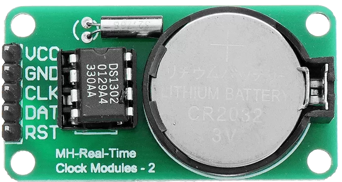
The DS1302 Real-Time Clock (RTC) is a widely used electronic component that provides accurate timekeeping and date information in a binary-coded decimal (BCD) format. It includes a built-in clock/calendar and 31 bytes of static RAM. The DS1302 communicates with microcontrollers via a simple serial interface and is commonly used in embedded systems, clocks, data loggers, and other devices that require timekeeping functionality.
Explore Projects Built with DS1302 RTC
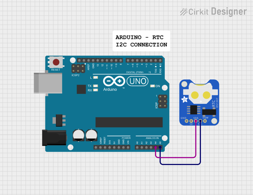
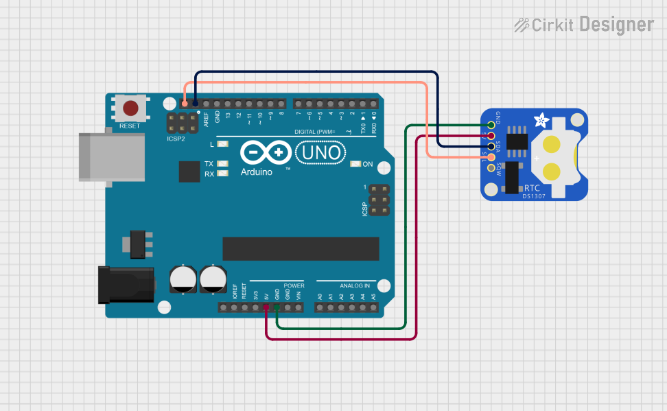
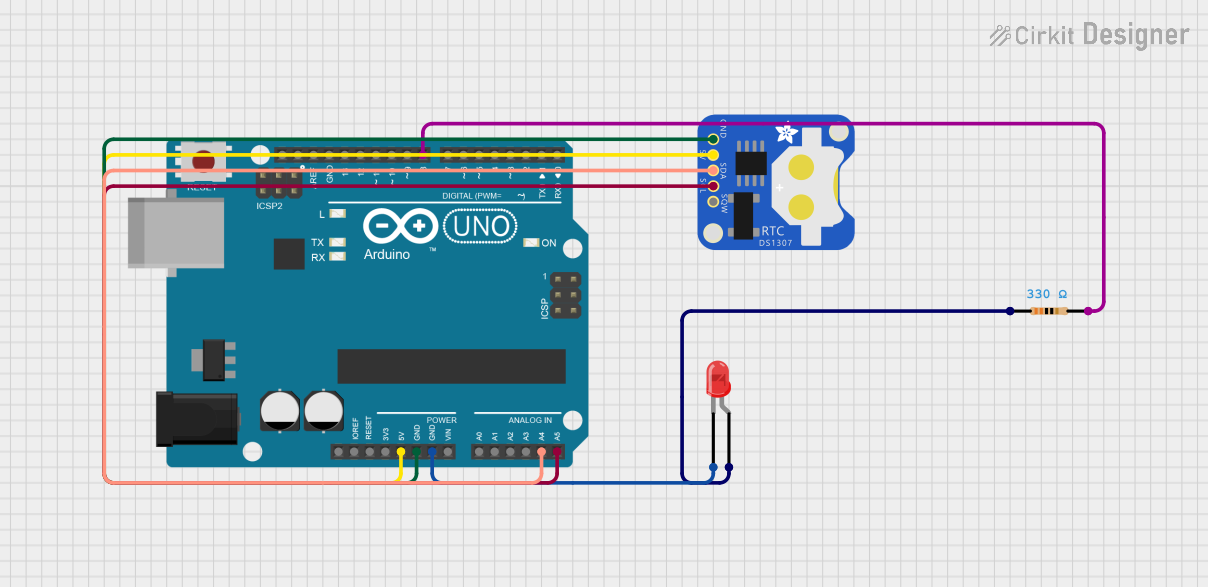

Explore Projects Built with DS1302 RTC
Common Applications and Use Cases
- Digital clocks and watches
- Data logging systems
- Time-stamping events
- Embedded systems requiring scheduled operations
Technical Specifications
Key Technical Details
- Voltage Supply: 2.0V to 5.5V
- Timekeeping Current: <1µA (typical at 2.0V)
- Interface: Serial (Simple 3-wire interface)
- Clock Format: HH:MM:SS (24-hour format)
- Calendar Format: YY-MM-DD-dd (Year, Month, Date, Day)
- Leap Year Compensation: Valid up to 2100
Pin Configuration and Descriptions
| Pin Number | Name | Description |
|---|---|---|
| 1 | X1 | Input for the 32.768 kHz crystal oscillator |
| 2 | X2 | Output for the 32.768 kHz crystal oscillator |
| 3 | GND | Ground pin |
| 4 | Vcc | Power supply pin (2.0V to 5.5V) |
| 5 | SCLK | Serial Clock Input |
| 6 | I/O | Serial Data Input/Output |
| 7 | CE | Chip Enable Input |
| 8 | Vbat | Backup Battery Input |
Usage Instructions
How to Use the DS1302 in a Circuit
- Power Supply: Connect the Vcc pin to a 2.0V to 5.5V power source and the GND pin to the ground.
- Crystal Oscillator: Attach a 32.768 kHz crystal oscillator to pins X1 and X2.
- Microcontroller Interface: Connect the SCLK, I/O, and CE pins to the corresponding digital I/O pins on your microcontroller.
- Backup Battery: To maintain timekeeping when the main power is off, connect a 3V coin cell battery to the Vbat pin.
Important Considerations and Best Practices
- Ensure that the power supply voltage is within the specified range to avoid damaging the DS1302.
- The backup battery should be non-rechargeable to prevent charging from the Vcc supply.
- Keep the crystal and DS1302 as close as possible to minimize noise and ensure accurate timekeeping.
- Use pull-up resistors on the I/O lines if required by your microcontroller's specifications.
Example Code for Arduino UNO
#include <DS1302.h>

// Initialize the DS1302
// CE pin -> Arduino Digital 2, I/O pin -> Arduino Digital 3, SCLK pin -> Arduino Digital 4
DS1302 rtc(2, 3, 4);

void setup() {
  Serial.begin(9600);
  rtc.halt(false);  // Enable the clock
  rtc.writeProtect(false);  // Disable write protection

  // Set the time to 12:00:00 (24hr format), date to 2023-04-01
  rtc.setDOW(SATURDAY);        // Set Day-of-Week to Saturday
  rtc.setTime(12, 0, 0);       // Set the time to 12:00:00 (24hr format)
  rtc.setDate(1, 4, 2023);     // Set the date to April 1, 2023
}

void loop() {
  // Print the current date and time to the Serial Monitor
  Serial.print(rtc.getDOWStr());
  Serial.print(" ");
  Serial.print(rtc.getDateStr());
  Serial.print(" -- ");
  Serial.println(rtc.getTimeStr());

  // Wait one second before repeating
  delay(1000);
}
Troubleshooting and FAQs
Common Issues Users Might Face
- Incorrect Timekeeping: Ensure the crystal oscillator is properly connected and not damaged.
- Communication Errors: Check the wiring between the DS1302 and the microcontroller, and ensure that the correct pins are used.
- Battery Issues: If the time resets after power loss, verify that the backup battery is correctly installed and has sufficient voltage.
Solutions and Tips for Troubleshooting
- Double-check all connections and ensure that solder joints are solid and not causing intermittent connections.
- Verify that the microcontroller's I/O pins are configured correctly for communication with the DS1302.
- If using a library, ensure that it is compatible with your version of the Arduino IDE and the microcontroller.
FAQs
Q: Can the DS1302 be used in a 12-hour format? A: Yes, the DS1302 can be configured to use a 12-hour format with an AM/PM indicator.
Q: How long will the backup battery last? A: The backup battery life depends on the battery capacity and the quality of the battery. Typically, a 3V coin cell battery can last several years.
Q: Is the DS1302 Y2K compliant? A: Yes, the DS1302 has leap year compensation and is valid up to the year 2100.