Cirkit Designer Logo
Cirkit Designer
Your all-in-one circuit design IDE
Home / 
Component Documentation

How to Use pule sensor: Examples, Pinouts, and Specs

Image of pule sensor
Cirkit Designer LogoDesign with pule sensor in Cirkit Designer

Introduction

The Pulse Sensor, manufactured by Atharv Banage, is a device designed to measure heart rate by detecting the pulse in the blood flow. This sensor is widely used in health monitoring systems, fitness trackers, and biofeedback applications. It provides an easy and non-invasive way to monitor heart rate, making it a popular choice for both hobbyists and professionals.

Explore Projects Built with pule sensor

Use Cirkit Designer to design, explore, and prototype these projects online. Some projects support real-time simulation. Click "Open Project" to start designing instantly!
Arduino UNO Based Heart Rate Monitor with OLED Display
Image of Dead Man's switch: A project utilizing pule sensor in a practical application
This circuit is designed to measure heart pulse rate using an Arduino UNO connected to a Heart Pulse Sensor. The sensor's signal is read by the Arduino's analog input A0, and the data is displayed on an OLED screen using I2C communication (SCL and SDA connected to A5 and A4 respectively). The embedded code reads the pulse signal, calculates the beats per minute (BPM), and dynamically displays the BPM value on the OLED.
Cirkit Designer LogoOpen Project in Cirkit Designer
Arduino-Based Air Quality Monitoring System with Bluetooth Connectivity
Image of Air quality part 2: A project utilizing pule sensor in a practical application
This circuit is an air quality monitoring system that uses an Arduino UNO to collect data from a PM2.5 air quality sensor (PMS5003) and an ozone sensor (MQ131). The collected data is then transmitted via an HC-05 Bluetooth module for remote monitoring, with a rocker switch used to control the power supply.
Cirkit Designer LogoOpen Project in Cirkit Designer
Arduino UNO-Based Lung Cancer Detector with Multiple Gas Sensors and LCD Display
Image of THE NEW LUN C: A project utilizing pule sensor in a practical application
This circuit is a lung cancer detector that uses six gas sensors connected to an Arduino UNO to monitor air quality. The sensor readings are displayed on a 20x4 LCD, and if any sensor value exceeds a predefined threshold, a buzzer and an LED are activated to alert the user.
Cirkit Designer LogoOpen Project in Cirkit Designer
Wi-Fi Controlled Smart Home Automation System with ESP8266, Sensors, and Actuators
Image of Parking System Project After Feedback: A project utilizing pule sensor in a practical application
This circuit is a multi-sensor monitoring system controlled by an ESP8266 NodeMCU. It integrates various sensors including PIR sensors, ultrasonic sensors, and a gas sensor, along with servos, LEDs, and a buzzer to detect motion, measure distance, and monitor gas levels, providing visual and auditory feedback.
Cirkit Designer LogoOpen Project in Cirkit Designer

Explore Projects Built with pule sensor

Use Cirkit Designer to design, explore, and prototype these projects online. Some projects support real-time simulation. Click "Open Project" to start designing instantly!
Image of Dead Man's switch: A project utilizing pule sensor in a practical application
Arduino UNO Based Heart Rate Monitor with OLED Display
This circuit is designed to measure heart pulse rate using an Arduino UNO connected to a Heart Pulse Sensor. The sensor's signal is read by the Arduino's analog input A0, and the data is displayed on an OLED screen using I2C communication (SCL and SDA connected to A5 and A4 respectively). The embedded code reads the pulse signal, calculates the beats per minute (BPM), and dynamically displays the BPM value on the OLED.
Cirkit Designer LogoOpen Project in Cirkit Designer
Image of Air quality part 2: A project utilizing pule sensor in a practical application
Arduino-Based Air Quality Monitoring System with Bluetooth Connectivity
This circuit is an air quality monitoring system that uses an Arduino UNO to collect data from a PM2.5 air quality sensor (PMS5003) and an ozone sensor (MQ131). The collected data is then transmitted via an HC-05 Bluetooth module for remote monitoring, with a rocker switch used to control the power supply.
Cirkit Designer LogoOpen Project in Cirkit Designer
Image of THE NEW LUN C: A project utilizing pule sensor in a practical application
Arduino UNO-Based Lung Cancer Detector with Multiple Gas Sensors and LCD Display
This circuit is a lung cancer detector that uses six gas sensors connected to an Arduino UNO to monitor air quality. The sensor readings are displayed on a 20x4 LCD, and if any sensor value exceeds a predefined threshold, a buzzer and an LED are activated to alert the user.
Cirkit Designer LogoOpen Project in Cirkit Designer
Image of Parking System Project After Feedback: A project utilizing pule sensor in a practical application
Wi-Fi Controlled Smart Home Automation System with ESP8266, Sensors, and Actuators
This circuit is a multi-sensor monitoring system controlled by an ESP8266 NodeMCU. It integrates various sensors including PIR sensors, ultrasonic sensors, and a gas sensor, along with servos, LEDs, and a buzzer to detect motion, measure distance, and monitor gas levels, providing visual and auditory feedback.
Cirkit Designer LogoOpen Project in Cirkit Designer

Technical Specifications

Key Technical Details

Parameter Value
Operating Voltage 3.3V - 5V
Operating Current 4mA
Output Signal Analog
Sensor Type Photoplethysmogram (PPG)
Dimensions 0.625" x 0.625" (16mm x 16mm)
Weight 1.2 grams

Pin Configuration and Descriptions

Pin Number Pin Name Description
1 VCC Power supply (3.3V - 5V)
2 GND Ground
3 SIG Analog signal output representing heart rate

Usage Instructions

How to Use the Component in a Circuit

  1. Power Supply: Connect the VCC pin to a 3.3V or 5V power supply.
  2. Ground: Connect the GND pin to the ground of your circuit.
  3. Signal Output: Connect the SIG pin to an analog input pin on your microcontroller (e.g., Arduino UNO).

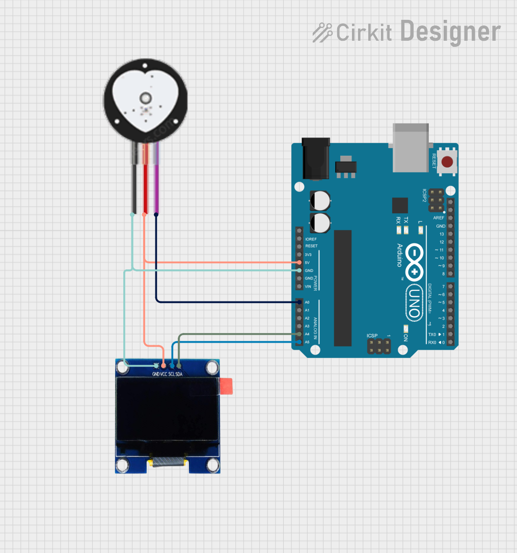
Example Circuit Diagram

+5V (Arduino) ----> VCC (Pulse Sensor)
GND (Arduino) ----> GND (Pulse Sensor)
A0 (Arduino) ----> SIG (Pulse Sensor)

Important Considerations and Best Practices

  • Placement: Ensure the sensor is placed on a part of the body where the pulse can be easily detected, such as the fingertip or earlobe.
  • Stability: Minimize movement during measurement to avoid noise and inaccurate readings.
  • Calibration: Calibrate the sensor for accurate readings by following the manufacturer's guidelines.

Sample Arduino Code

/*
  Pulse Sensor Example Code
  This code reads the analog signal from the Pulse Sensor and prints the
  heart rate to the Serial Monitor.
*/

const int pulsePin = A0; // Pulse Sensor connected to analog pin A0
int signal;              // Variable to store the analog signal value

void setup() {
  Serial.begin(9600);    // Initialize serial communication at 9600 baud
  pinMode(pulsePin, INPUT); // Set pulsePin as an input
}

void loop() {
  signal = analogRead(pulsePin); // Read the analog signal from the sensor
  Serial.println(signal);        // Print the signal value to the Serial Monitor
  delay(10);                     // Small delay for stability
}

Troubleshooting and FAQs

Common Issues Users Might Face

  1. No Signal Detected:

    • Solution: Ensure the sensor is properly connected and placed on a suitable part of the body. Check the power supply and ground connections.
  2. Noisy Signal:

    • Solution: Minimize movement and ensure the sensor is securely placed. Use a low-pass filter to reduce noise in the signal.
  3. Inaccurate Readings:

    • Solution: Calibrate the sensor according to the manufacturer's guidelines. Ensure the sensor is clean and free from obstructions.

FAQs

Q1: Can the Pulse Sensor be used with microcontrollers other than Arduino?

  • A1: Yes, the Pulse Sensor can be used with any microcontroller that has an analog input pin and supports the operating voltage range.

Q2: How do I clean the Pulse Sensor?

  • A2: Use a soft, dry cloth to gently clean the sensor. Avoid using water or any cleaning agents.

Q3: What is the maximum distance between the sensor and the microcontroller?

  • A3: It is recommended to keep the distance as short as possible to avoid signal degradation. Typically, a few inches to a foot is ideal.

Q4: Can the Pulse Sensor be used for continuous monitoring?

  • A4: Yes, the Pulse Sensor is designed for continuous monitoring. However, ensure proper placement and calibration for accurate readings.

This documentation provides a comprehensive guide to using the Pulse Sensor by Atharv Banage. Whether you are a beginner or an experienced user, this guide will help you effectively integrate the sensor into your projects.