Cirkit Designer Logo
Cirkit Designer
Your all-in-one circuit design IDE
Home / 
Component Documentation

How to Use MAX471: Examples, Pinouts, and Specs

Image of MAX471
Cirkit Designer LogoDesign with MAX471 in Cirkit Designer

Introduction

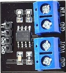
The MAX471 is a high-side current sensor that provides a precise analog voltage output proportional to the current passing through the load. This sensor is designed to monitor the current in a variety of applications, including battery chargers, power supplies, and portable devices. Its high-side measurement allows for simple circuit integration without disrupting the ground path of the measured load.

Explore Projects Built with MAX471

Use Cirkit Designer to design, explore, and prototype these projects online. Some projects support real-time simulation. Click "Open Project" to start designing instantly!
Sequential Timer-Controlled Relay Switching Circuit
Image of Mark Murry Fantasy Lights: A project utilizing MAX471 in a practical application
This circuit is a sequential relay timer utilizing three 555 timers configured as astable multivibrators to generate timing pulses. These pulses clock a 4017 decade counter, which sequentially activates multiple relay modules. Timing adjustments are possible through potentiometers and fixed resistors, while capacitors set the oscillation frequency.
Cirkit Designer LogoOpen Project in Cirkit Designer
Battery-Powered Emergency Alert System with NUCLEO-F072RB, SIM800L, and GPS NEO 6M
Image of women safety: A project utilizing MAX471 in a practical application
This circuit is an emergency alert system that uses a NUCLEO-F072RB microcontroller to send SMS alerts and make calls via a SIM800L GSM module, while obtaining location data from a GPS NEO 6M module. The system is powered by a Li-ion battery and includes a TP4056 module for battery charging and protection, with a rocker switch to control power to the microcontroller.
Cirkit Designer LogoOpen Project in Cirkit Designer
Arduino UNO Based Automated Pill Dispenser with GSM Notifications and RTC Scheduling
Image of MEDICAL DISPENSER: A project utilizing MAX471 in a practical application
This circuit is designed as an automated pill dispenser with scheduled alerts and manual pill-taking confirmation. It uses an Arduino UNO to control three servos for dispensing pills at predefined times, indicated by an I2C LCD screen and a DS3231 RTC for timekeeping. The system can send SMS notifications via the Sim800l GSM module and provides reminders with a piezo buzzer, while user interactions are handled through pushbuttons.
Cirkit Designer LogoOpen Project in Cirkit Designer
Teensy 4.1-Based Multi-Channel Potentiometer Interface with 74HC4051 Mux and AMS1117 3.3V Regulator
Image of redrum: A project utilizing MAX471 in a practical application
This circuit features a Teensy 4.1 microcontroller interfaced with a SparkFun 74HC4051 8-channel multiplexer to read multiple rotary potentiometers. The AMS1117 3.3V voltage regulator provides a stable 3.3V supply to the multiplexer and potentiometers, while electrolytic and ceramic capacitors are used for power supply filtering and stabilization.
Cirkit Designer LogoOpen Project in Cirkit Designer

Explore Projects Built with MAX471

Use Cirkit Designer to design, explore, and prototype these projects online. Some projects support real-time simulation. Click "Open Project" to start designing instantly!
Image of Mark Murry Fantasy Lights: A project utilizing MAX471 in a practical application
Sequential Timer-Controlled Relay Switching Circuit
This circuit is a sequential relay timer utilizing three 555 timers configured as astable multivibrators to generate timing pulses. These pulses clock a 4017 decade counter, which sequentially activates multiple relay modules. Timing adjustments are possible through potentiometers and fixed resistors, while capacitors set the oscillation frequency.
Cirkit Designer LogoOpen Project in Cirkit Designer
Image of women safety: A project utilizing MAX471 in a practical application
Battery-Powered Emergency Alert System with NUCLEO-F072RB, SIM800L, and GPS NEO 6M
This circuit is an emergency alert system that uses a NUCLEO-F072RB microcontroller to send SMS alerts and make calls via a SIM800L GSM module, while obtaining location data from a GPS NEO 6M module. The system is powered by a Li-ion battery and includes a TP4056 module for battery charging and protection, with a rocker switch to control power to the microcontroller.
Cirkit Designer LogoOpen Project in Cirkit Designer
Image of MEDICAL DISPENSER: A project utilizing MAX471 in a practical application
Arduino UNO Based Automated Pill Dispenser with GSM Notifications and RTC Scheduling
This circuit is designed as an automated pill dispenser with scheduled alerts and manual pill-taking confirmation. It uses an Arduino UNO to control three servos for dispensing pills at predefined times, indicated by an I2C LCD screen and a DS3231 RTC for timekeeping. The system can send SMS notifications via the Sim800l GSM module and provides reminders with a piezo buzzer, while user interactions are handled through pushbuttons.
Cirkit Designer LogoOpen Project in Cirkit Designer
Image of redrum: A project utilizing MAX471 in a practical application
Teensy 4.1-Based Multi-Channel Potentiometer Interface with 74HC4051 Mux and AMS1117 3.3V Regulator
This circuit features a Teensy 4.1 microcontroller interfaced with a SparkFun 74HC4051 8-channel multiplexer to read multiple rotary potentiometers. The AMS1117 3.3V voltage regulator provides a stable 3.3V supply to the multiplexer and potentiometers, while electrolytic and ceramic capacitors are used for power supply filtering and stabilization.
Cirkit Designer LogoOpen Project in Cirkit Designer

Common Applications and Use Cases

  • Battery-powered device current monitoring
  • Power management systems
  • Overcurrent protection circuits
  • Portable device power consumption analysis
  • Solar power monitoring systems

Technical Specifications

Key Technical Details

  • Supply Voltage (Vcc): 4.5V to 36V
  • Sensing Voltage Range: 0V to +36V
  • Output Voltage: Proportional to current (1V/A)
  • Maximum Current Sensing: 3A (MAX471CSA), 10A (MAX471ESA)
  • Quiescent Current: 100 µA
  • Accuracy: ±1.5% full-scale
  • Operating Temperature Range: -40°C to +85°C

Pin Configuration and Descriptions

Pin Number Name Description
1 OUT Analog voltage output proportional to the sensed current
2 RS+ Connect to the positive side of the current-sensing resistor
3 RS- Connect to the load side of the current-sensing resistor
4 GND Ground reference for the sensor
5 Vcc Supply voltage input for the sensor

Usage Instructions

How to Use the MAX471 in a Circuit

  1. Connect the Vcc pin to a power supply within the range of 4.5V to 36V.
  2. Connect the GND pin to the system ground.
  3. Insert the MAX471 in series with the load, ensuring that the current flows from RS+ to RS-.
  4. The OUT pin will output an analog voltage proportional to the current through the load. Connect this to an analog input on a microcontroller for measurement.

Important Considerations and Best Practices

  • Ensure that the current does not exceed the maximum rating of the sensor.
  • Avoid placing the sensor near high-temperature sources to prevent thermal drift.
  • Use a decoupling capacitor close to the Vcc pin to minimize power supply noise.
  • Keep the analog signal path from OUT to the microcontroller as short as possible to reduce noise pickup.

Example Code for Arduino UNO

const int analogInPin = A0; // Analog input pin for MAX471 OUT
float sensorValue = 0;      // Value read from the sensor
float current = 0;          // Calculated current

void setup() {
  Serial.begin(9600); // Initialize serial communication at 9600 bits per second
}

void loop() {
  // Read the sensor value
  sensorValue = analogRead(analogInPin);
  // Convert the analog reading to current in amperes
  current = sensorValue * (5.0 / 1023.0); // Assuming a 5V ADC reference voltage

  // Print the current to the Serial Monitor
  Serial.print("Current sensed: ");
  Serial.print(current);
  Serial.println(" A");

  delay(1000); // Wait for a second for next reading
}

Troubleshooting and FAQs

Common Issues Users Might Face

  • Inaccurate Readings: Ensure that the power supply is stable and within the specified range. Check for proper grounding and stable connections.
  • No Output Voltage: Verify that the sensor is correctly powered and that the current is flowing through the sensor from RS+ to RS-.
  • Overheating: Continuous operation at high currents close to the sensor's maximum rating can lead to overheating. Ensure adequate ventilation and consider heat sinking if necessary.

Solutions and Tips for Troubleshooting

  • Calibration: If the output seems off, calibrate the sensor by comparing its output with a known current source.
  • Noise Reduction: Use shielded cables for the OUT pin connection and keep the analog path away from digital signals or power lines.
  • Sensor Placement: Place the sensor as close to the power source as possible to reduce the potential for voltage drops affecting the measurement.

FAQs

Q: Can the MAX471 be used for AC current measurement? A: No, the MAX471 is designed for DC current measurement only.

Q: What is the voltage drop across the sensor? A: The MAX471 has a very low voltage drop, typically around 100 µV at full-scale current.

Q: How can I increase the maximum current sensing capability? A: For currents higher than the sensor's rating, an external current shunt resistor with a lower resistance value can be used in conjunction with the MAX471 to increase the range. However, this requires recalibration and careful consideration of the power dissipation across the shunt.