How to Use MKE-M01 LED Module: Examples, Pinouts, and Specs
Introduction
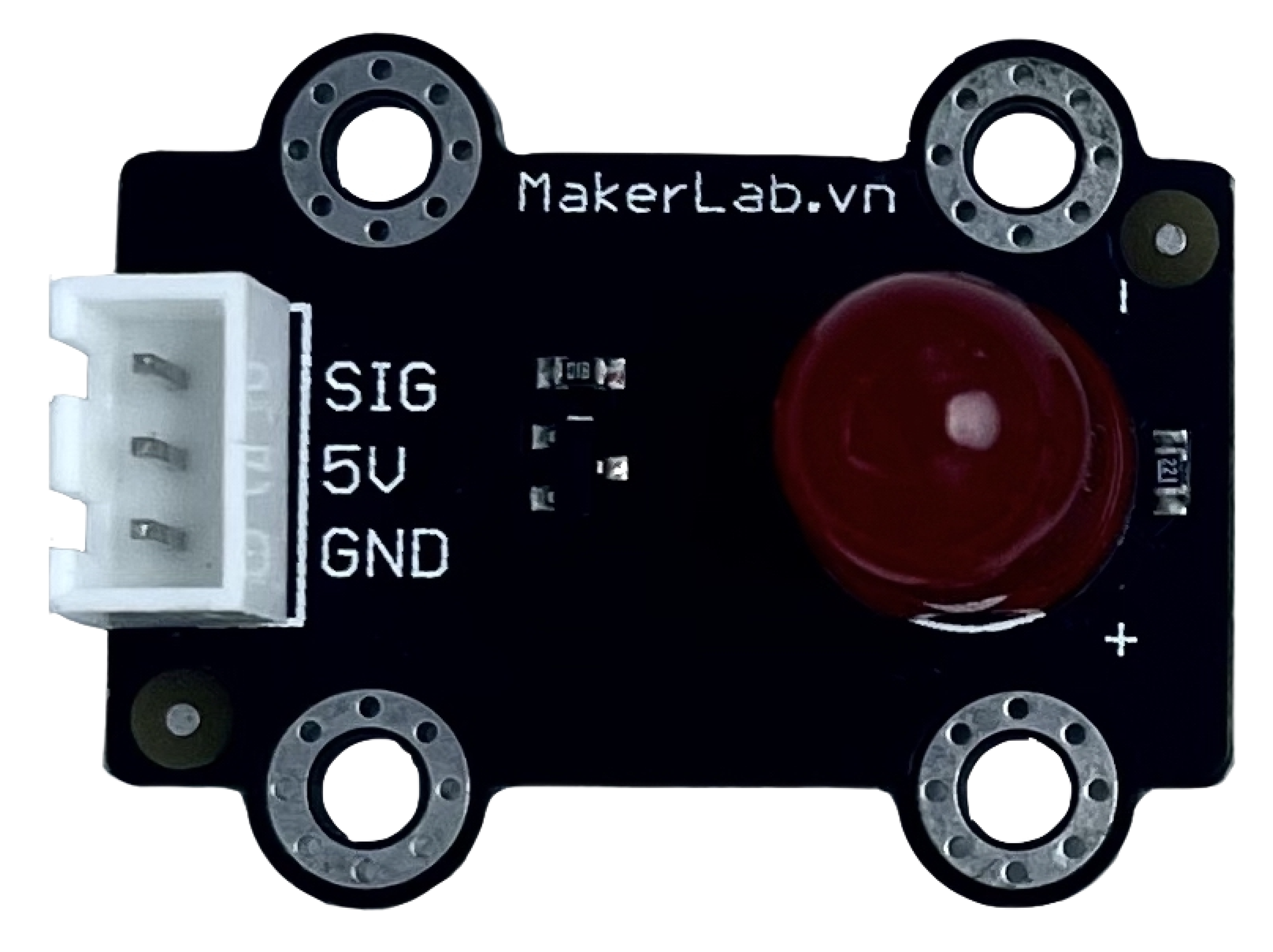
The MKE-M01 LED Module is a versatile and compact electronic component designed for emitting light when powered by an electric current. This module is widely used in DIY projects, educational settings, and prototyping due to its ease of use and low power requirements. Common applications include status indicators, backlighting, and simple visual outputs in electronic circuits.
Explore Projects Built with MKE-M01 LED Module
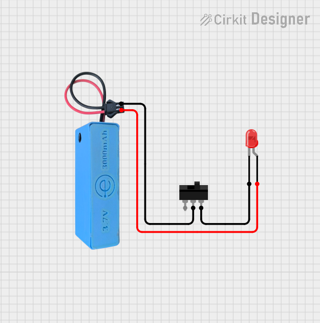
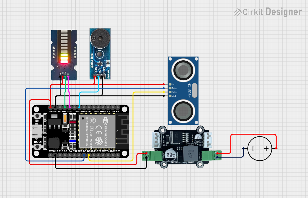
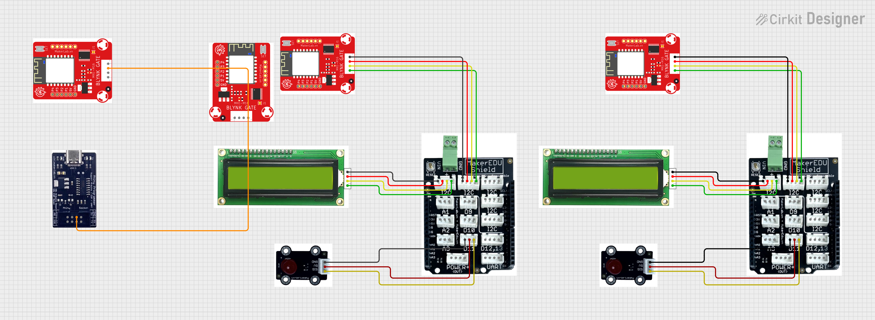

Explore Projects Built with MKE-M01 LED Module
Technical Specifications
General Characteristics
- Operating Voltage: Typically 3.3V to 5V
- Current Consumption: 10-20 mA (depending on LED color and intensity)
- Brightness: Varies with current and LED color
- Lifespan: Typically > 50,000 hours
Pin Configuration and Descriptions
| Pin Number | Description | Notes |
|---|---|---|
| 1 | Anode (+) | Connect to positive power supply |
| 2 | Cathode (-) | Connect to ground |
Usage Instructions
Connecting the LED Module to a Circuit
- Power Supply: Connect the anode pin of the LED module to a suitable power supply (3.3V to 5V). Ensure that the voltage does not exceed the maximum rating to prevent damage.
- Current Limiting: Place a current-limiting resistor in series with the LED to prevent excessive current flow. A typical value is 220 ohms for a 5V supply.
- Ground Connection: Connect the cathode pin to the ground of the power supply.
Best Practices
- Resistor Calculation: To calculate the appropriate resistor value, use Ohm's Law:
R = (V_supply - V_LED) / I_LED, whereV_LEDis the forward voltage of the LED andI_LEDis the desired current. - Polarity: Ensure correct polarity when connecting the LED module. Reversing the polarity may damage the LED.
- Heat Dissipation: Although LEDs are efficient, they can generate heat. Ensure adequate ventilation around the module.
Example Code for Arduino UNO
// Define the LED pin
const int ledPin = 13; // Most Arduino UNOs have an onboard LED on pin 13

void setup() {
  // Set the LED pin as an output
  pinMode(ledPin, OUTPUT);
}

void loop() {
  // Turn the LED on
  digitalWrite(ledPin, HIGH);
  delay(1000); // Wait for 1 second
  // Turn the LED off
  digitalWrite(ledPin, LOW);
  delay(1000); // Wait for 1 second
}
This example code will blink the onboard LED on the Arduino UNO. If using the MKE-M01 LED Module, connect it to pin 13 with a suitable resistor in series.
Troubleshooting and FAQs
Common Issues
- LED Not Lighting Up: Check the polarity of the connections. Ensure the anode is connected to the positive supply and the cathode to the ground.
- Dim LED: The current-limiting resistor may be too high. Verify the resistor value with the calculation mentioned above.
- LED Burnt Out: The voltage may have exceeded the LED's rating, or the current-limiting resistor was omitted.
FAQs
Q: Can I power the LED module directly from an Arduino pin? A: Yes, Arduino pins can source enough current for an LED, but always use a current-limiting resistor.
Q: What happens if I reverse the polarity of the LED module? A: LEDs are diodes and will not conduct in reverse bias. Reversing the polarity will prevent it from lighting up and may damage the LED if the reverse voltage is too high.
Q: How do I choose the correct resistor value? A: Use the formula provided in the best practices section, considering the supply voltage, LED forward voltage, and desired current.
Q: Can I use PWM to control the brightness of the LED? A: Yes, you can use pulse-width modulation (PWM) on a digital pin of the Arduino to control the brightness of the LED.
For further assistance, please refer to the Arduino forums or the community support for the MKE-M01 LED Module.