How to Use кнопка 2 пина: Examples, Pinouts, and Specs
Introduction
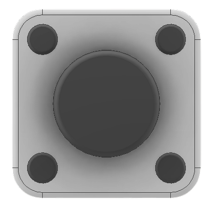
The кнопка 2 пина (2-pin button switch) is a simple, momentary push-button switch used to open or close an electrical circuit. When pressed, the button completes the circuit, allowing current to flow. When released, the circuit is broken, stopping the flow of current. This component is widely used in electronic projects for user input, such as turning devices on/off, triggering events, or navigating menus.
Explore Projects Built with кнопка 2 пина

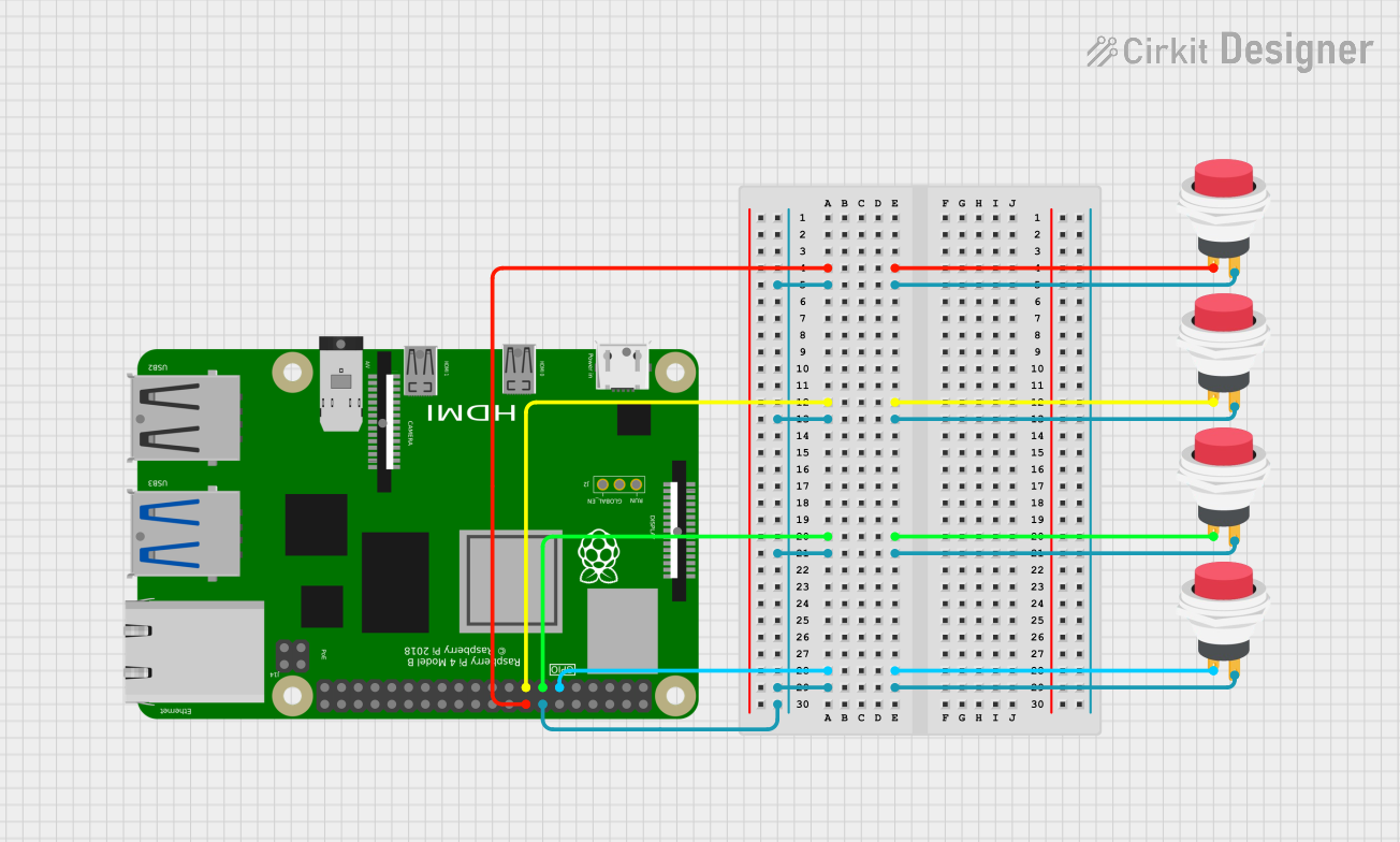
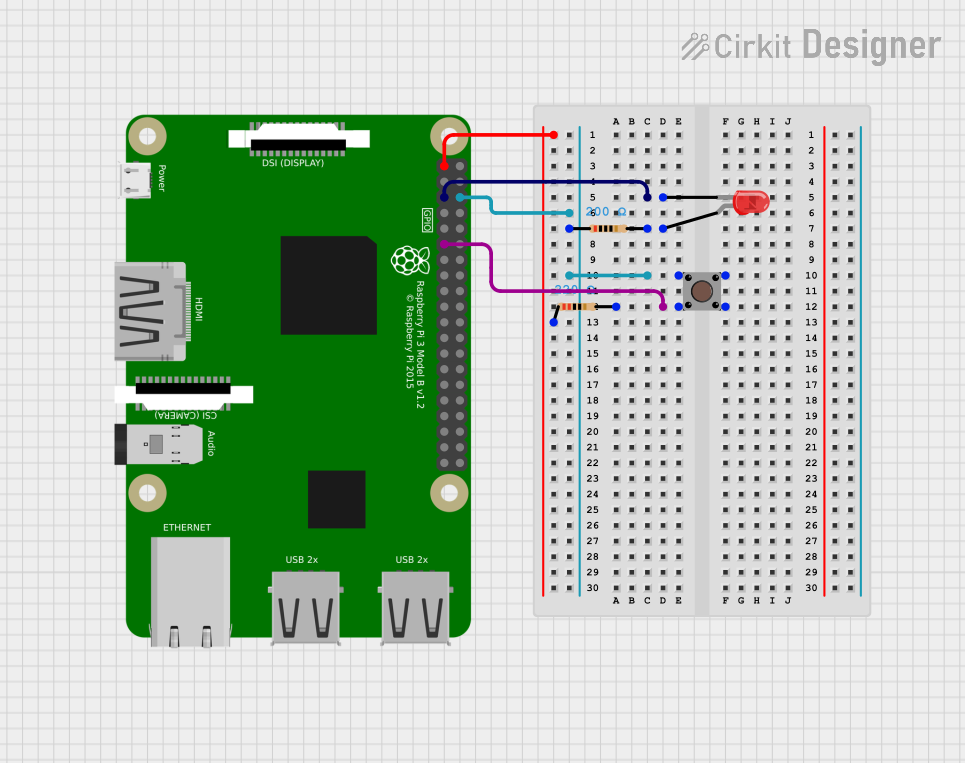
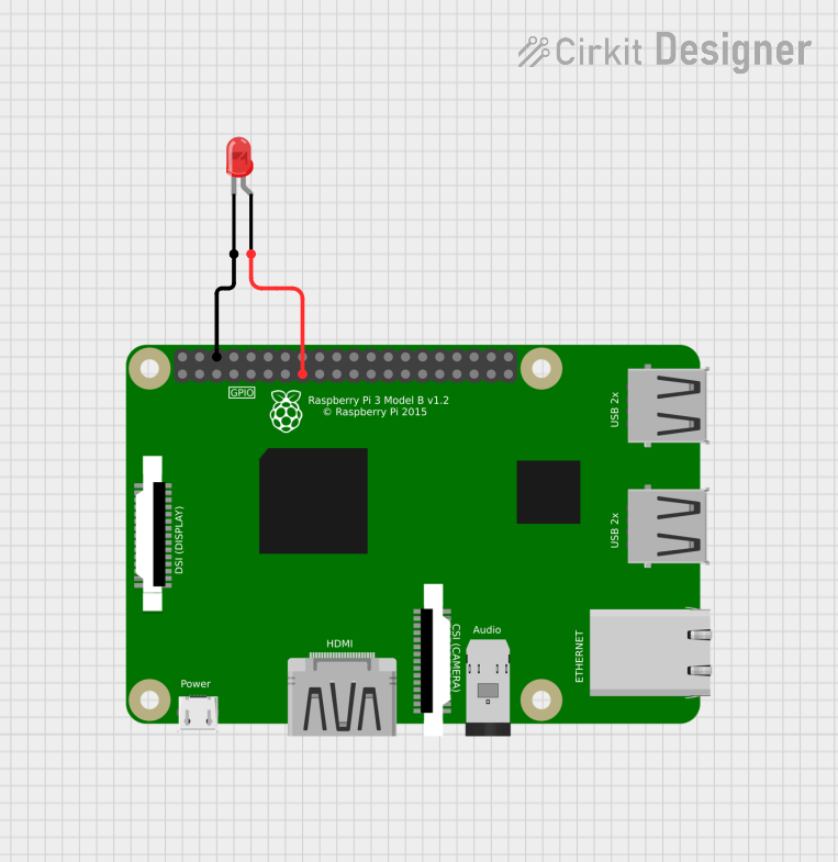
Explore Projects Built with кнопка 2 пина
Common Applications and Use Cases
- User input for microcontroller-based projects (e.g., Arduino, Raspberry Pi)
- Reset or power buttons in electronic devices
- Triggering events in robotics or automation systems
- Simple on/off control in low-power circuits
Technical Specifications
- Type: Momentary push-button switch
- Pins: 2
- Operating Voltage: Typically 3.3V to 5V (compatible with most microcontrollers)
- Current Rating: Up to 50mA (suitable for low-power circuits)
- Contact Resistance: ≤ 100mΩ
- Insulation Resistance: ≥ 100MΩ
- Mechanical Durability: Up to 100,000 actuations
- Dimensions: Varies by model, typically 6mm x 6mm x 5mm
Pin Configuration and Descriptions
The кнопка 2 пина has two pins, which are not polarized. This means there is no specific orientation required when connecting it to a circuit. Below is the pin description:
| Pin Number | Description |
|---|---|
| 1 | One terminal of the switch contact |
| 2 | The other terminal of the switch contact |
When the button is pressed, the two pins are electrically connected, completing the circuit.
Usage Instructions
How to Use the Component in a Circuit
Connect the Button:
- Connect one pin of the button to the input pin of your microcontroller or circuit.
- Connect the other pin to ground (GND).
- Optionally, use a pull-up resistor (typically 10kΩ) between the input pin and the positive voltage (Vcc) to ensure a stable signal when the button is not pressed.
Debounce the Button:
- Mechanical buttons can produce noise or "bouncing" when pressed or released. Use a capacitor (e.g., 0.1µF) in parallel with the button or implement software debouncing in your code.
Test the Circuit:
- When the button is pressed, the input pin should detect a LOW signal (if using a pull-up resistor). When released, the input pin should detect a HIGH signal.
Example Circuit with Arduino UNO
Below is an example of how to connect and use the кнопка 2 пина with an Arduino UNO:
Circuit Diagram
- Connect one pin of the button to Arduino digital pin 2.
- Connect the other pin to GND.
- Add a 10kΩ pull-up resistor between digital pin 2 and 5V.
Arduino Code
// Define the pin connected to the button
const int buttonPin = 2;
// Define the pin connected to the LED
const int ledPin = 13;

// Variable to store the button state
int buttonState = 0;

void setup() {
  // Set the button pin as input with internal pull-up resistor
  pinMode(buttonPin, INPUT_PULLUP);
  // Set the LED pin as output
  pinMode(ledPin, OUTPUT);
}

void loop() {
  // Read the state of the button
  buttonState = digitalRead(buttonPin);

  // If the button is pressed (LOW signal), turn on the LED
  if (buttonState == LOW) {
    digitalWrite(ledPin, HIGH); // Turn on the LED
  } else {
    digitalWrite(ledPin, LOW);  // Turn off the LED
  }
}
Important Considerations and Best Practices
- Pull-up Resistor: Always use a pull-up resistor to avoid floating input states.
- Debouncing: Implement hardware or software debouncing to ensure reliable operation.
- Voltage and Current Ratings: Do not exceed the specified voltage and current ratings to avoid damaging the button.
- Mechanical Durability: Avoid excessive force or rapid pressing to prolong the button's lifespan.
Troubleshooting and FAQs
Common Issues and Solutions
Button Not Responding:
- Check the wiring and ensure the button is properly connected.
- Verify that the pull-up resistor is in place and correctly connected.
Unstable or Erratic Behavior:
- This is likely due to button bouncing. Add a capacitor in parallel with the button or implement software debouncing.
Button Always Reads as Pressed:
- Ensure the pull-up resistor is connected between the input pin and Vcc.
- Check for short circuits or damaged components.
Button Always Reads as Not Pressed:
- Verify that the button is functioning correctly by testing it with a multimeter.
- Ensure the input pin is properly configured in the code.
FAQs
Q: Can I use the кнопка 2 пина with a 3.3V microcontroller?
A: Yes, the button is compatible with 3.3V systems. Ensure the pull-up resistor is appropriately sized.
Q: Do I need a pull-up resistor if my microcontroller has internal pull-ups?
A: No, if your microcontroller supports internal pull-ups (e.g., Arduino), you can enable them in the code.
Q: How do I debounce the button in software?
A: Use a delay or a state-checking algorithm in your code to filter out noise caused by bouncing.
Q: Can I use this button for high-power applications?
A: No, the кнопка 2 пина is designed for low-power circuits. Use a relay or transistor for high-power switching.
By following this documentation, you can effectively integrate the кнопка 2 пина into your electronic projects!