
How to Use LCD 20x4 I2C: Examples, Pinouts, and Specs
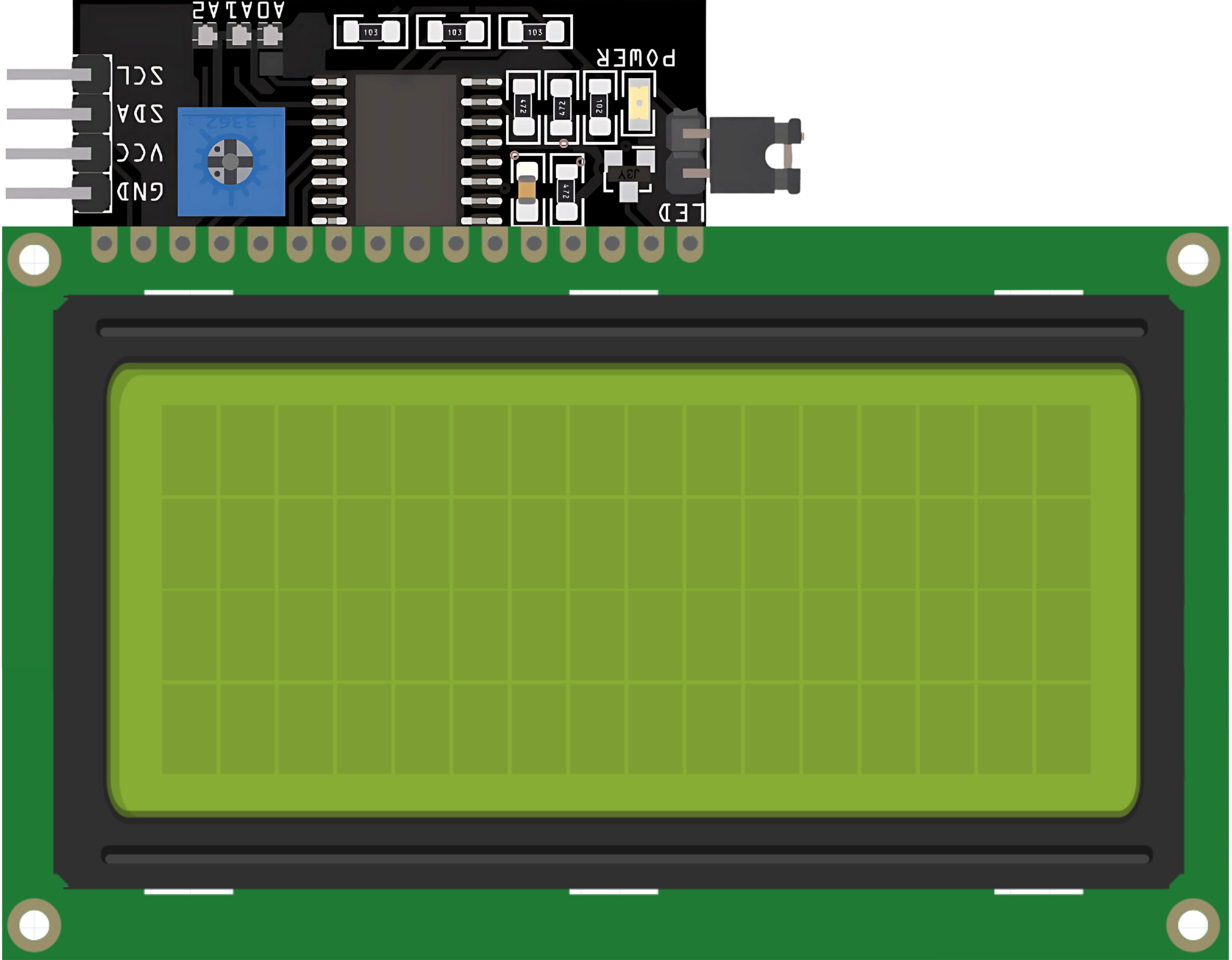
 Design with LCD 20x4 I2C in Cirkit Designer
Introduction
The LCD 20x4 I2C is a 20-character by 4-line Liquid Crystal Display module that utilizes I2C (Inter-Integrated Circuit) communication. This module is designed for easy integration with microcontrollers, requiring only two data lines (SDA and SCL) for communication. It is widely used in projects where a compact and efficient display is needed to show text, numbers, or simple symbols.
Explore Projects Built with LCD 20x4 I2C
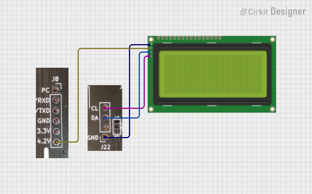 Open Project in Cirkit Designer
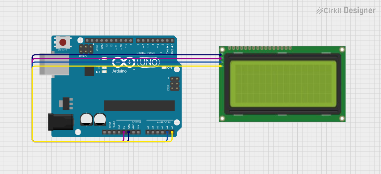 Open Project in Cirkit Designer
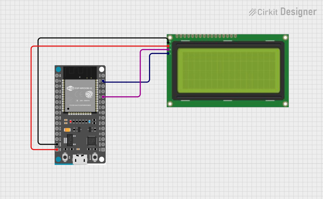 Open Project in Cirkit Designer
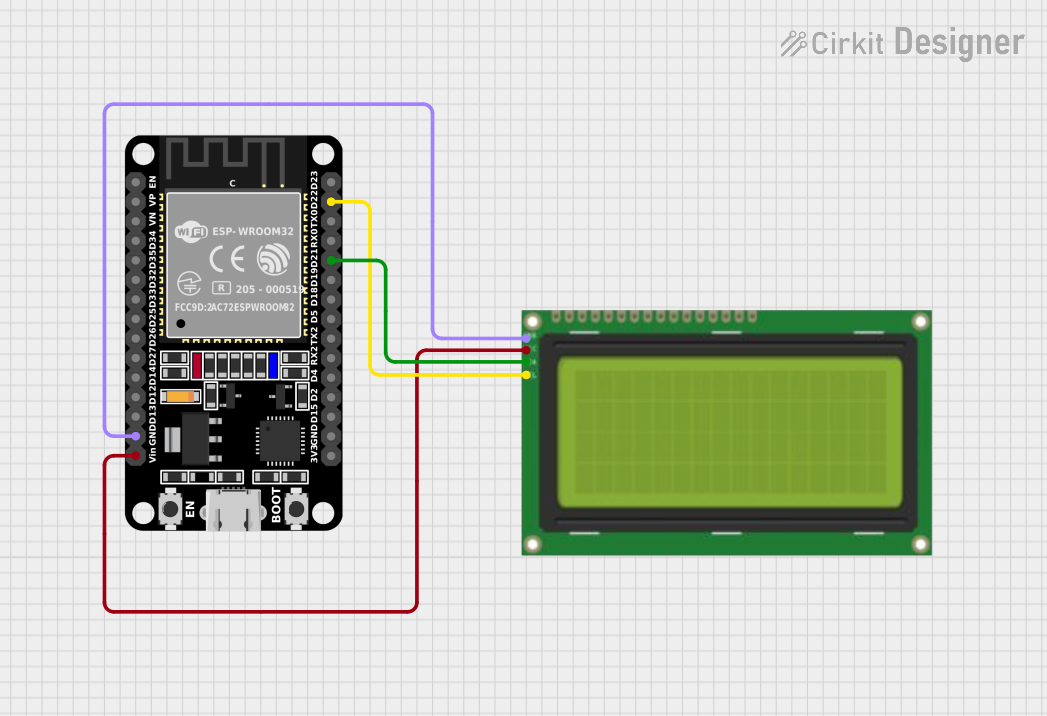 Open Project in Cirkit Designer
Explore Projects Built with LCD 20x4 I2C
Open Project in Cirkit DesignerOpen Project in Cirkit DesignerOpen Project in Cirkit DesignerOpen Project in Cirkit DesignerCommon Applications and Use Cases
- Embedded systems and microcontroller projects
- Home automation displays
- IoT devices for status monitoring
- Industrial control panels
- Educational and prototyping purposes
Technical Specifications
Key Technical Details
| Parameter | Value |
|---|---|
| Display Type | 20x4 Character LCD |
| Communication Protocol | I2C (Inter-Integrated Circuit) |
| Operating Voltage | 5V DC |
| Backlight | LED (adjustable brightness) |
| Contrast Adjustment | Potentiometer (onboard) |
| I2C Address (Default) | 0x27 (can vary by module) |
| Operating Temperature | -20°C to +70°C |
| Dimensions | ~98mm x 60mm x 12mm |
Pin Configuration and Descriptions
The LCD 20x4 I2C module typically has a 4-pin interface for I2C communication. Below is the pinout:
| Pin | Name | Description |
|---|---|---|
| 1 | GND | Ground (0V) |
| 2 | VCC | Power supply (5V DC) |
| 3 | SDA | Serial Data Line for I2C communication |
| 4 | SCL | Serial Clock Line for I2C communication |
Usage Instructions
How to Use the Component in a Circuit
Wiring the LCD 20x4 I2C to a Microcontroller:
- Connect the
GNDpin of the LCD to the ground pin of the microcontroller. - Connect the
VCCpin of the LCD to the 5V power pin of the microcontroller. - Connect the
SDApin of the LCD to the SDA pin of the microcontroller (e.g., A4 on Arduino UNO). - Connect the
SCLpin of the LCD to the SCL pin of the microcontroller (e.g., A5 on Arduino UNO).
- Connect the
Install Required Libraries:
- For Arduino, install the
LiquidCrystal_I2Clibrary from the Arduino Library Manager.
- For Arduino, install the
Adjust the Contrast:
- Use the onboard potentiometer to adjust the contrast of the display until the characters are clearly visible.
Important Considerations and Best Practices
- Ensure the I2C address of the LCD matches the address in your code. The default is usually
0x27, but it may vary depending on the module. - Use pull-up resistors (typically 4.7kΩ to 10kΩ) on the SDA and SCL lines if they are not already included on the module.
- Avoid exceeding the operating voltage (5V) to prevent damage to the module.
- Keep the I2C bus length as short as possible to maintain signal integrity.
Example Code for Arduino UNO
Below is an example code to display text on the LCD 20x4 I2C using an Arduino UNO:
#include <Wire.h>                // Include the Wire library for I2C communication
#include <LiquidCrystal_I2C.h>   // Include the LiquidCrystal_I2C library

// Initialize the LCD with I2C address 0x27 and 20x4 dimensions
LiquidCrystal_I2C lcd(0x27, 20, 4);

void setup() {
  lcd.begin();                   // Initialize the LCD
  lcd.backlight();               // Turn on the backlight
  lcd.setCursor(0, 0);           // Set cursor to the first column, first row
  lcd.print("Hello, World!");    // Print text on the first row
  lcd.setCursor(0, 1);           // Set cursor to the first column, second row
  lcd.print("LCD 20x4 I2C");     // Print text on the second row
  lcd.setCursor(0, 2);           // Set cursor to the first column, third row
  lcd.print("Line 3 Example");   // Print text on the third row
  lcd.setCursor(0, 3);           // Set cursor to the first column, fourth row
  lcd.print("Line 4 Example");   // Print text on the fourth row
}

void loop() {
  // No actions in the loop for this example
}
Troubleshooting and FAQs
Common Issues and Solutions
No Display or Blank Screen:
- Verify the wiring connections, especially the
GNDandVCCpins. - Adjust the contrast using the onboard potentiometer.
- Verify the wiring connections, especially the
Incorrect or Garbled Characters:
- Ensure the I2C address in the code matches the module's address.
- Check for loose or faulty connections on the SDA and SCL lines.
Backlight Not Turning On:
- Confirm that the
lcd.backlight()function is called in the code. - Check the power supply voltage (should be 5V).
- Confirm that the
I2C Address Not Detected:
- Use an I2C scanner sketch to detect the correct address of the module.
- Ensure the SDA and SCL lines are properly connected.
FAQs
Q: Can I use the LCD 20x4 I2C with a 3.3V microcontroller?
A: Yes, but you will need a logic level shifter to safely interface the 3.3V microcontroller with the 5V LCD module.
Q: How do I change the I2C address of the module?
A: The I2C address can be changed by modifying the solder jumpers on the back of the module. Refer to the module's datasheet for details.
Q: Can I display custom characters on the LCD?
A: Yes, the LiquidCrystal_I2C library supports creating and displaying custom characters. Refer to the library documentation for examples.
Q: What is the maximum cable length for I2C communication?
A: The maximum length depends on the pull-up resistor values and the operating frequency, but it is generally recommended to keep the cable length under 1 meter for reliable communication.