How to Use Serial : Examples, Pinouts, and Specs
Introduction
The Serial communication interface, manufactured by DFRobot, is a widely used method for transmitting data one bit at a time over a single channel. It is a fundamental communication protocol in electronics, enabling devices to exchange information efficiently. Serial communication is commonly used in microcontrollers, sensors, and modules to connect peripherals such as displays, GPS modules, and wireless communication devices.
Explore Projects Built with Serial
Explore Projects Built with Serial
Common Applications and Use Cases
- Communication between microcontrollers and sensors
- Data transfer between computers and embedded systems
- Connecting GPS modules, Bluetooth modules, and Wi-Fi modules
- Debugging and monitoring system performance
- Interfacing with serial-enabled displays and actuators
Technical Specifications
The DFRobot Serial interface adheres to standard serial communication protocols and is compatible with a wide range of devices. Below are the key technical details:
Key Technical Details
- Communication Protocol: UART (Universal Asynchronous Receiver-Transmitter)
- Voltage Levels: 3.3V or 5V (depending on the device)
- Baud Rate: Configurable, typically 9600 bps to 115200 bps
- Data Bits: 8 bits
- Parity: None, Even, or Odd (configurable)
- Stop Bits: 1 or 2 (configurable)
- Flow Control: None, Hardware (RTS/CTS), or Software (XON/XOFF)
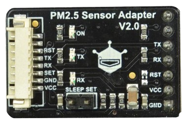
Pin Configuration and Descriptions
The Serial interface typically uses a 4-pin configuration. Below is the pinout:
| Pin Name | Description | Direction |
|---|---|---|
| TX (Transmit) | Sends data to the connected device | Output |
| RX (Receive) | Receives data from the connected device | Input |
| GND | Ground reference | - |
| VCC | Power supply (3.3V or 5V) | - |
Usage Instructions
How to Use the Component in a Circuit
Connect the Pins:
- Connect the
TXpin of the Serial interface to theRXpin of the receiving device. - Connect the
RXpin of the Serial interface to theTXpin of the transmitting device. - Connect the
GNDpin to the ground of the circuit. - Provide the appropriate voltage (3.3V or 5V) to the
VCCpin.
- Connect the
Configure the Baud Rate:
- Ensure that both devices in the communication setup are configured to use the same baud rate, data bits, parity, and stop bits.
Write and Read Data:
- Use a microcontroller or computer to send and receive data through the Serial interface.
Important Considerations and Best Practices
- Voltage Compatibility: Ensure that the voltage levels of the Serial interface match the connected device to avoid damage.
- Signal Integrity: Use short and shielded cables for high-speed communication to minimize noise and signal degradation.
- Baud Rate Matching: Both devices must use the same baud rate for successful communication.
- Avoid Cross-Talk: Keep the Serial lines away from high-power or noisy components.
Example: Using Serial with Arduino UNO
Below is an example of how to use the Serial interface with an Arduino UNO to send and receive data:
// Example: Sending and receiving data via Serial on Arduino UNO

void setup() {
  Serial.begin(9600); // Initialize Serial communication at 9600 baud
  while (!Serial) {
    // Wait for the Serial port to connect (useful for native USB boards)
  }
  Serial.println("Serial communication initialized!"); // Send a message
}

void loop() {
  if (Serial.available() > 0) {
    // Check if data is available to read
    char receivedChar = Serial.read(); // Read the incoming character
    Serial.print("Received: "); // Print the received character
    Serial.println(receivedChar);
  }
  delay(100); // Small delay to avoid overwhelming the Serial buffer
}
Troubleshooting and FAQs
Common Issues and Solutions
No Data Transmission:
- Cause: Incorrect wiring of TX and RX pins.
- Solution: Verify that the
TXpin of one device is connected to theRXpin of the other device, and vice versa.
Garbage Data Received:
- Cause: Mismatched baud rate between devices.
- Solution: Ensure both devices are configured with the same baud rate.
Device Not Responding:
- Cause: Incorrect voltage levels or loose connections.
- Solution: Check the voltage levels and ensure all connections are secure.
Intermittent Communication:
- Cause: Noise or interference in the Serial lines.
- Solution: Use shorter cables and ensure proper grounding.
FAQs
Q: Can I use the Serial interface for long-distance communication?
- A: Serial communication is not ideal for long distances due to signal degradation. For longer distances, consider using RS-485 or other differential signaling protocols.
Q: What is the maximum baud rate supported?
- A: The maximum baud rate depends on the device and cable quality. Most devices support up to 115200 bps.
Q: Can I connect multiple devices to a single Serial interface?
- A: Standard Serial communication is point-to-point. For multiple devices, consider using protocols like I2C or SPI.
Q: How do I debug Serial communication issues?
- A: Use a logic analyzer or Serial monitor to inspect the data being transmitted and received.
This documentation provides a comprehensive guide to using the DFRobot Serial interface effectively. For further assistance, refer to the manufacturer's datasheet or support resources.