How to Use Adafruit Bonsai Buckaroo: Examples, Pinouts, and Specs
Introduction
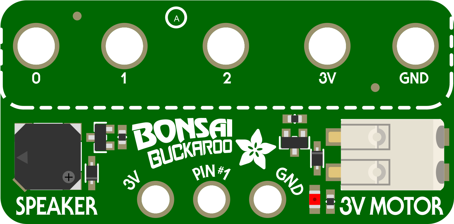
The Adafruit Bonsai Buckaroo is a versatile power and control board designed for small robotic projects and educational purposes. It simplifies the process of powering and controlling motors, servos, and other actuators. With its compact size and ease of use, the Bonsai Buckaroo is ideal for hobbyists, educators, and students looking to explore the world of robotics and electronics.
Explore Projects Built with Adafruit Bonsai Buckaroo
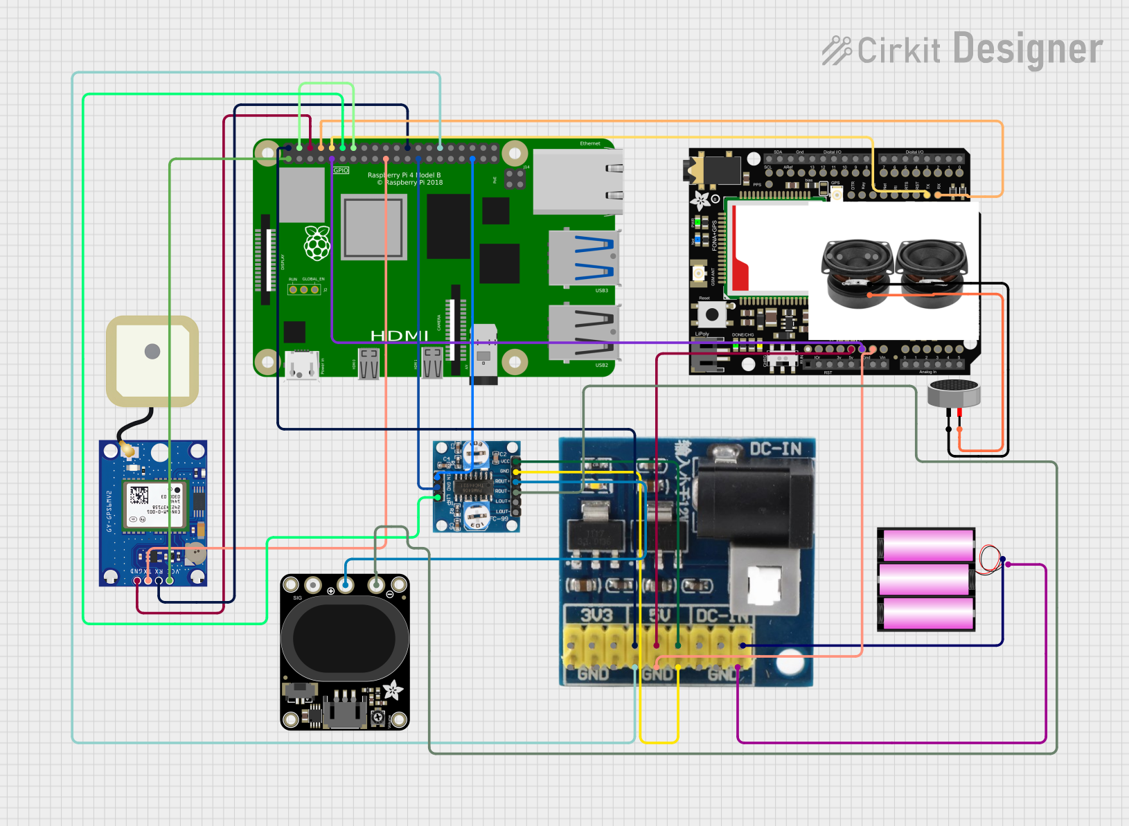
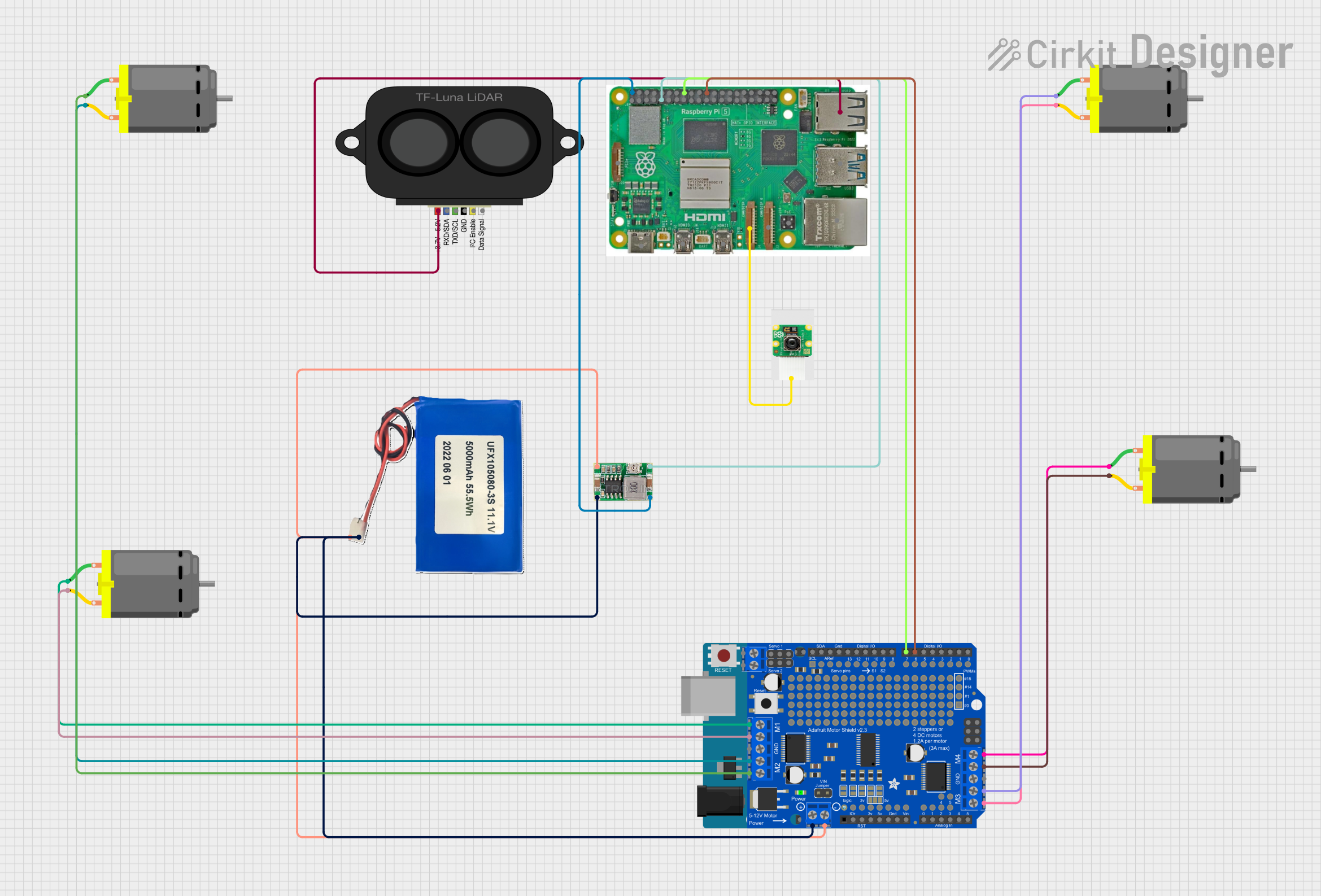
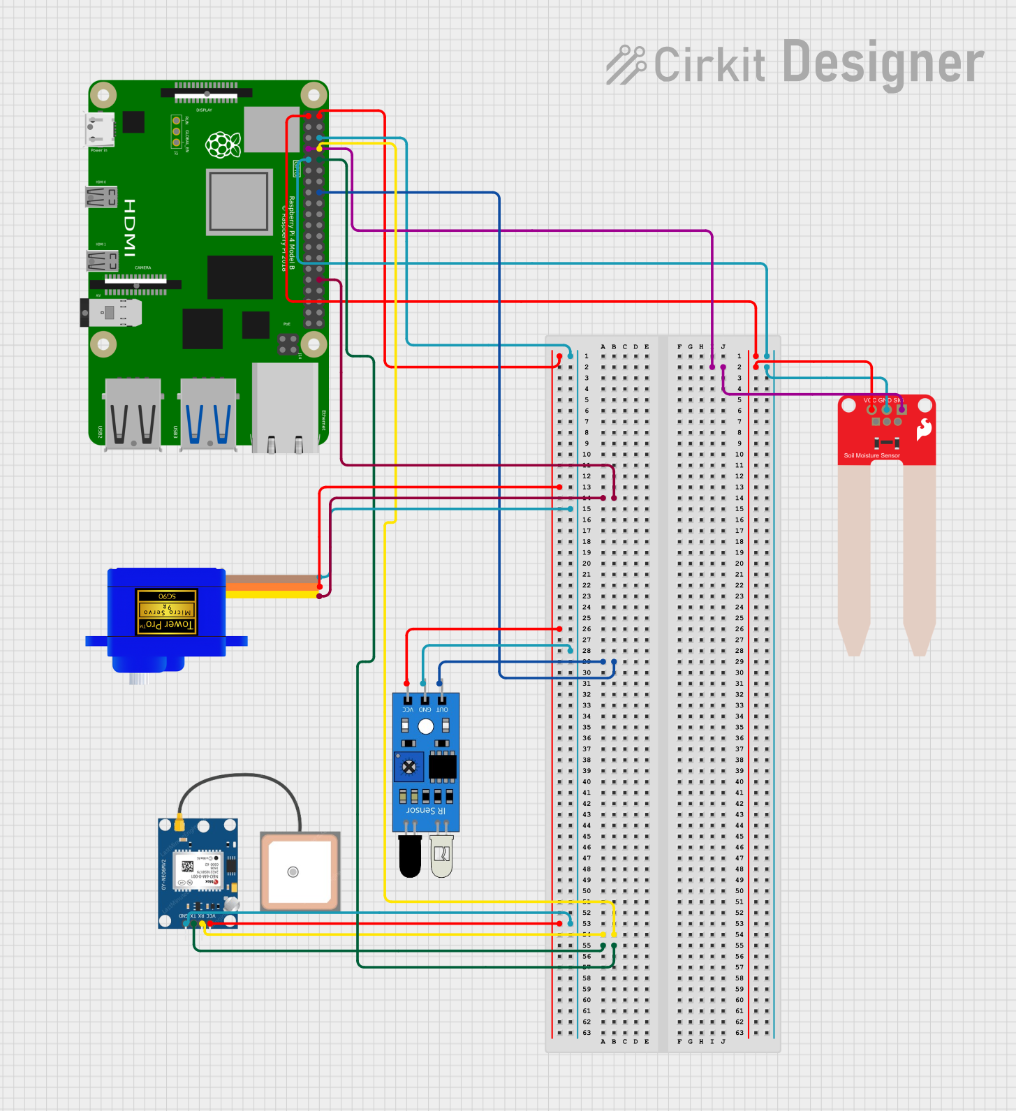
Explore Projects Built with Adafruit Bonsai Buckaroo
Common Applications and Use Cases
- Educational robotics projects
- DIY hobbyist projects
- Small-scale automation tasks
- Prototyping robotic components
Technical Specifications
Key Technical Details
- Input Voltage: 3.3V to 5V
- Output Voltage: 3.3V regulated for logic
- Continuous Current: Up to 1A for motors
- PWM Outputs: 2 channels for servo control
Pin Configuration and Descriptions
| Pin Number | Description | Notes |
|---|---|---|
| 1 | GND (Ground) | Common ground for all connections |
| 2 | VIN (Voltage Input) | 3.3V to 5V input voltage |
| 3 | 3V3 (3.3V Output) | Regulated output for logic |
| 4 | A1 (Analog Input 1) | For sensor input |
| 5 | A2 (Analog Input 2) | For sensor input |
| 6 | D1 (Digital I/O 1) | For digital signals |
| 7 | D2 (Digital I/O 2) | For digital signals |
| 8 | PWM1 (PWM Output 1) | For servo or LED control |
| 9 | PWM2 (PWM Output 2) | For servo or LED control |
| 10 | Motor+ (Motor Power Positive) | Connect to motor positive lead |
| 11 | Motor- (Motor Power Negative) | Connect to motor negative lead |
Usage Instructions
How to Use the Component in a Circuit
Powering the Board:
- Connect the VIN pin to a 3.3V to 5V power source.
- Ensure the ground from the power source is connected to the GND pin.
Connecting Motors:
- Attach the positive lead of the motor to the Motor+ pin.
- Connect the negative lead of the motor to the Motor- pin.
Controlling Servos:
- Connect the servo's power wire (usually red) to the 3V3 pin.
- Attach the servo's ground wire (usually brown or black) to the GND pin.
- Connect the servo's signal wire (usually orange or yellow) to one of the PWM outputs.
Important Considerations and Best Practices
- Do not exceed the recommended voltage and current specifications to avoid damaging the board.
- When controlling motors, ensure that the total current draw does not exceed 1A.
- Use appropriate wire gauge for connections, especially for power and motor connections.
- Keep the board away from conductive materials that could cause shorts.
- Always disconnect power before making or altering connections.
Troubleshooting and FAQs
Common Issues Users Might Face
- Motor not running: Check connections to the Motor+ and Motor- pins and ensure the power supply is adequate.
- Servo not responding: Verify that the servo is connected correctly to the PWM output and is receiving power from the 3V3 pin.
- Board not powering on: Ensure that the VIN pin is connected to a proper power source and that the GND pin is connected to the ground of the power source.
Solutions and Tips for Troubleshooting
- Double-check all connections for proper orientation and secure fit.
- Measure the input voltage to ensure it falls within the specified range.
- If using PWM outputs, verify that the control signal is within the expected range for the device being controlled.
FAQs
Q: Can I control more than one motor with the Bonsai Buckaroo? A: The Bonsai Buckaroo is designed to control a single motor. For multiple motors, consider using additional boards or a board with multiple motor driver channels.
Q: What is the maximum servo load I can control with the PWM outputs? A: The maximum load will depend on the servo's specifications. Ensure the servo's power requirements do not exceed the board's 3.3V output capabilities.
Q: Can I use the Bonsai Buckaroo with an Arduino UNO? A: Yes, the Bonsai Buckaroo can be used with an Arduino UNO or any other compatible microcontroller platform.
Example Code for Arduino UNO
// Example code to control a servo connected to the Bonsai Buckaroo with an Arduino UNO

#include <Servo.h>

Servo myservo;  // create servo object to control a servo

void setup() {
  myservo.attach(9);  // attaches the servo on pin 9 to the servo object
}

void loop() {
  myservo.write(90);  // sets the servo position to 90 degrees
  delay(1000);        // waits for a second
  myservo.write(0);   // sets the servo position to 0 degrees
  delay(1000);        // waits for a second
}
Remember to adjust the myservo.attach() function to match the PWM pin used on the Bonsai Buckaroo. The example assumes the servo control signal is connected to PWM1 (pin 9 on the Arduino UNO).